
Microtome Cassette Clamp Having An Air Channel For Dissipating The Heat Of A Cooling Element, And Microtome

a cooling element and cassette clamp technology, applied in the field of microtome cassette clamps, can solve the problems of peltier element performance decline, impaired feed mechanism function, etc., and achieve the effect of accurate and simple manner

Inactive Publication Date: 2011-11-03
LEICA BIOSYST NUSSLOCH
View PDF11 Cites 6 Cited by
  • Summary
  • Abstract
  • Description
  • Claims
  • Application Information

AI Technical Summary

Benefits of technology

The present invention provides a device and method for cooling tissue samples on a microtome. The device includes a cooling element with a cold region facing the tissue sample and a hot region facing away from the tissue sample. The device has a first air channel for dissipating the heat released by the cooling element and a ventilation device for generating an air flow in the first air channel. The interaction of the cooling element, the first air channel, and the ventilation device helps prevent the tissue samples from heating up to unnecessarily high levels, keeping them in an optimum condition and ensuring proper functioning of the feed mechanism for advancing the tissue samples. The device may also have a surface made of antistatic material to prevent static charge buildup. The invention also provides a microtome with the cooling device. The technical effects of the invention include improved accuracy and simplicity in tissue sample sectioning and prevention of heat-related damage to the tissue samples.

Problems solved by technology

During prolonged operation of the microtome, the material of the cooling device, of the microtome, or of a feed mechanism of the microtome may be heated to such a degree that the tissue samples are no longer sufficiently cooled and / or that the functioning of the feed mechanism is impaired.
In addition, the performance of the Peltier element decreases the longer it is continuously used, because the heat generated in the Peltier element is not consistently dissipated.

Method used


Image

  • Microtome Cassette Clamp Having An Air Channel For Dissipating The Heat Of A Cooling Element, And Microtome
  • Microtome Cassette Clamp Having An Air Channel For Dissipating The Heat Of A Cooling Element, And Microtome
  • Microtome Cassette Clamp Having An Air Channel For Dissipating The Heat Of A Cooling Element, And Microtome

Examples


Embodiment Construction

[0022]Elements having the same design or function are identified by the same reference numerals throughout the figures.

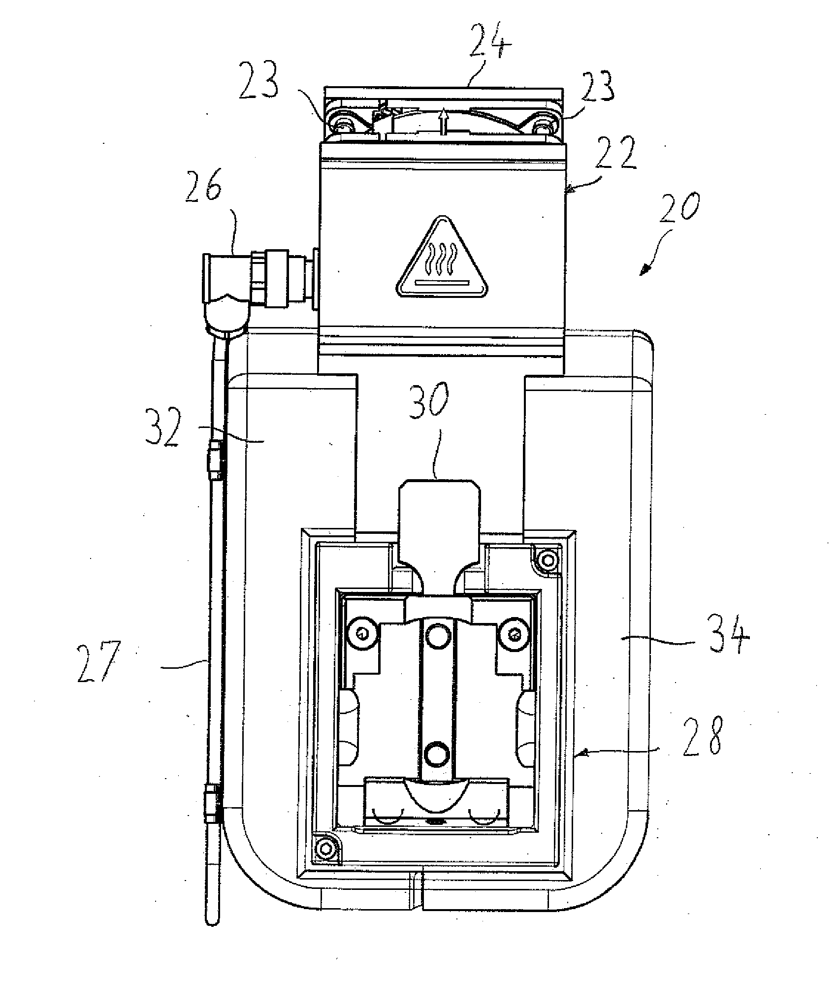
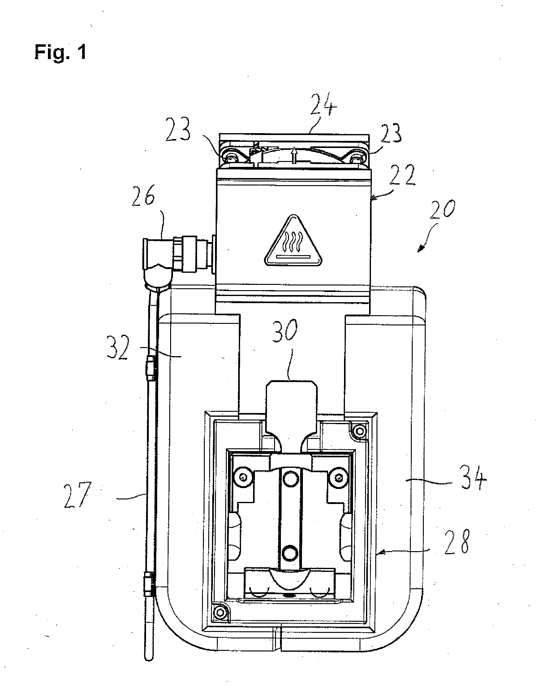
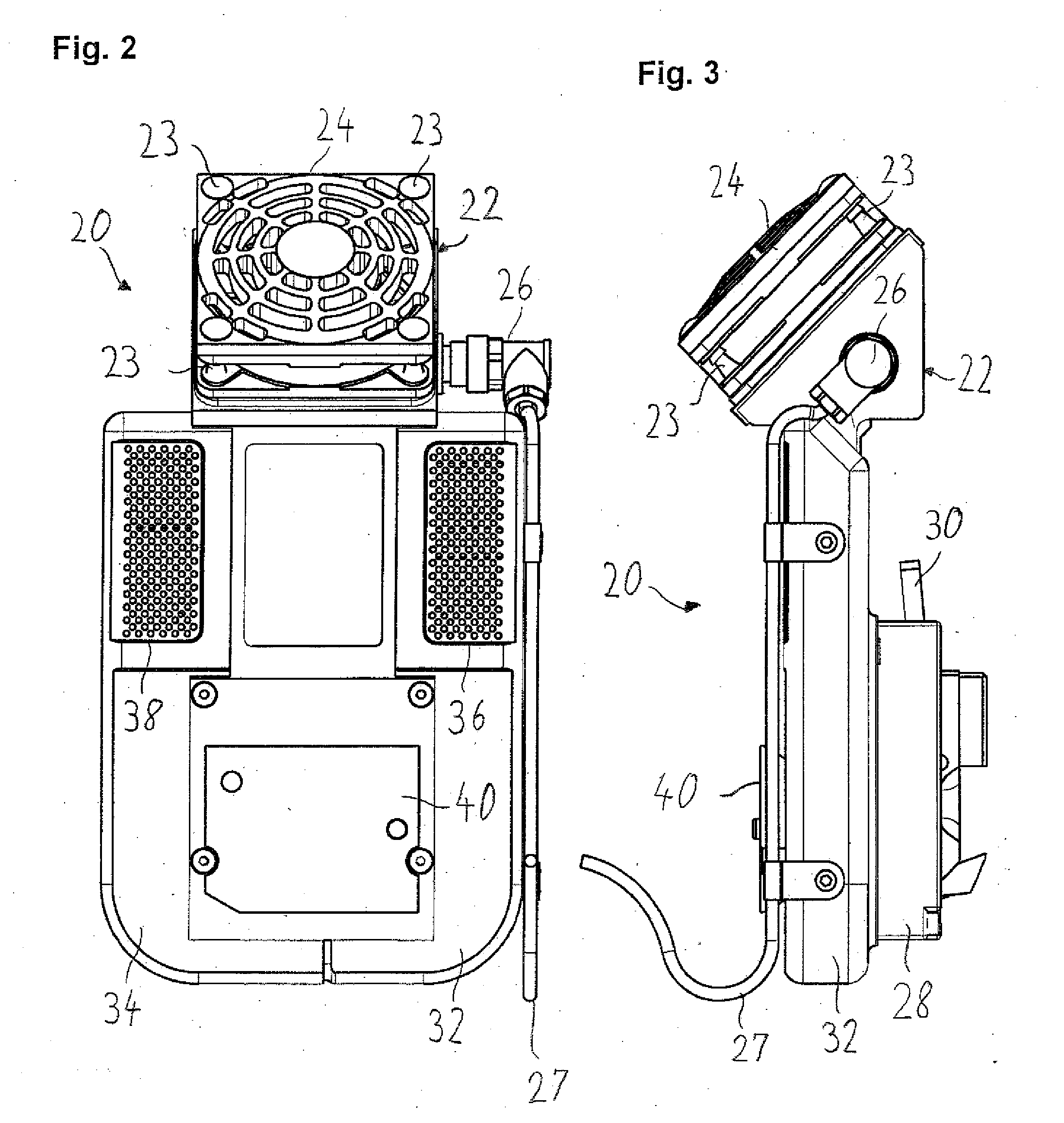
[0023]FIG. 1 shows a device for cooling tissue samples (not shown). During use, device 20 is attached to a microtome (not shown) for sectioning tissue samples. The tissue samples are embedded in a support medium, such as paraffin. A paraffin block containing tissue samples is held in a cassette. Device 20 serves to receive and hold the cassettes containing the tissue samples during sectioning of the tissue samples and to cool them during the sectioning operation.

[0024]Device 20 includes a ventilation device 22. Ventilation device 22 has a cover 24, which is attached by fastening elements 23 to a base plate of ventilation device 22. Ventilation device 22 has a rotor (not shown). The rotor is driven electrically and coupled to a power supply via a connector 26 and a cable 27. In addition, a control line may extend through connector 26 and a cable 27 for purposes of co...


PUM


Abstract

A device for cooling a tissue sample on a microtome includes a cooling element (44), a first air channel (32), and a ventilation device (22). The cooling element (44) has a cold region facing the tissue sample and a hot region which faces away from the tissue sample and dissipates the heat generated in the cooling element (44) to the ambient environment. The first air channel (32) is provided for dissipating the heat released by the cooling element (44). The ventilation device (22) generates an air flow through the first air channel (32), said air flow absorbing and removing the heat released via the hot region of the cooling element (44).

Description

CROSS REFERENCE TO RELATED APPLICATIONS[0001]This application claims priority of German patent application number 10 2010 016 728.2 filed Apr. 30, 2010, the entire disclosure of which is incorporated by reference herein.FIELD OF THE INVENTION[0002]The present invention relates to a device and a method for cooling a tissue sample on a microtome. The present invention also relates to a microtome which includes said device for cooling tissue samples so as to provide for cooling of tissue samples to be sectioned.BACKGROUND OF THE INVENTION[0003]Before tissue samples can be examined using a microscope, they generally have to be prepared for this purpose. To this end, the tissue samples are embedded in a support medium, such as paraffin. The paraffin blocks containing the embedded tissue samples are held in cassettes, which are storable in suitable cassette magazines. Subsequently, the embedded tissue samples are cut with a microtome into extremely thin sections, which can then be examine...

Claims


Application Information

Patent Timeline
Patent Type & Authority Applications(United States)
IPC IPC(8): F25D25/00F25B21/02B26D7/08F25D31/00
CPCF25B21/02B01L7/00G01N1/06
Inventor WESTERHOFF, KARL-HEINZDORENKAMP, CLAUDIALORENZ, CHRISTIANGOEDECKE, EVA
Owner LEICA BIOSYST NUSSLOCH
Learn More