Method and circuit for adjusting a resistance in an integrated circuit

a technology of integrated circuits and resistances, applied in the direction of solid-state devices, instruments, semiconductor/solid-state device details, etc., can solve the problems of large-area fixed resistances which are difficult to control, nonlinear resistance characteristics, and large area required for this resistan

Inactive Publication Date: 2006-05-30
POLARIS INNOVATIONS LTD
View PDF8 Cites 6 Cited by
  • Summary
  • Abstract
  • Description
  • Claims
  • Application Information

AI Technical Summary

Benefits of technology

[0008]It is, therefore, the object of the present invention to provide a resistance component for integration in an integrated circuit, the resistance value of which can be adjusted in a simple and accurate manner and which requires only a small area.
[0015]In the range of adjustable resistances in the antifuse structure, there is a range in which the adjustable resistance is essentially independent of an operating current. The operating current is the current which is impressed into the resistance by a circuit in which the resistance is used. In this manner, a constant resistance can be ensured even when the currents of the resistance changes.
[0016]It is preferably provided that the programming current is applied to an external connection of the integrated circuit. This has the advantage that internal generation of a programming current in the integrated circuit is not required and thus a programming circuit necessary for this can be saved in the integrated circuit.
[0020]The fuse structure is preferably constructed as an antifuse structure which has a dielectric area as resistance area. For this purpose, it can be provided that the programming circuit has a current source in order to conduct through the resistance a programming current which increases with time. When the predetermined resistance value is reached, the current source can be switched off in order to retain the resistance value set. During the increase in programming current, the changing resistance value set in each case is continuously measured and it is determined, whether the set resistance value corresponds to the desired resistance value to be set. If the desired resistance value has been reached, the resistance value which has just been reached can be retained by switching off the current source. This makes it possible to implement a programming circuit which is as simple as possible and by means of which a resistance formed from an antifuse structure can be adjusted.
[0024]According to a further aspect of the present invention, a method for using an antifuse component as resistance element with a resistance which can be freely adjustable within a resistance range by means of a programming current is provided. This makes it possible to use antifuse components not only as permanent adjustment memories for adjustment values but also for the resistance elements which are used in an integrated circuit.

Problems solved by technology

This leads to a large-area fixed resistance which is hard to control.
This leads to a nonlinear resistance characteristic and to a relatively large area being required for this resistance.

Method used


Image

  • Method and circuit for adjusting a resistance in an integrated circuit
  • Method and circuit for adjusting a resistance in an integrated circuit
  • Method and circuit for adjusting a resistance in an integrated circuit

Examples


Embodiment Construction

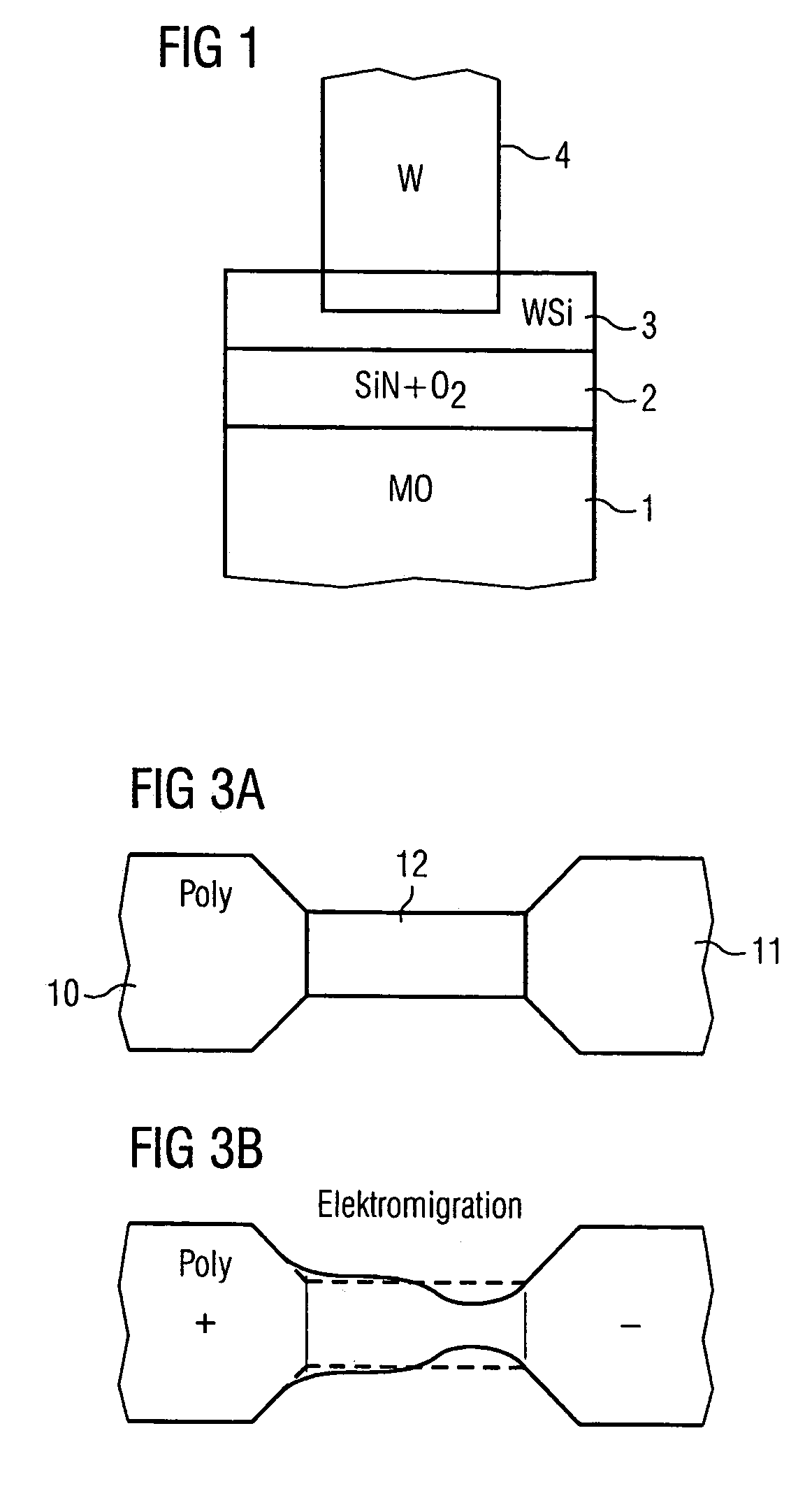
[0031]FIG. 1 shows an antifuse structure. It has a first conductive layer 1 which is preferably built from a metalizing layer. Above this, a dielectric layer 2 is applied which has, e.g., a dielectric constant ∈R=5.5. Naturally, dielectric layers having other dielectric constants can also be used. The dielectric layer 2 can have silicon nitride in which oxygen molecules are implanted.

[0032]Above this, a second conductive layer 3 is deposited which is contacted via a conductor connection 4. The second conductive layer 3 preferably has tungsten silicate but can also have other materials which are conductive. The conductor connection 4 is preferably constructed of tungsten, but other electrically conductive materials are also suitable for it, such as, e.g., aluminum, copper etc.

[0033]After such an antifuse structure has been produced, the antifuse structure is initially nonconductive since a nonconductive dielectric is arranged between the first conductive layer 1 and the second conduc...


PUM


Abstract

A method for adjusting a resistance in an integrated circuit, the resistance having a first conductive area and a second conductive area between which a dielectric area is arranged, a programming current being conducted through the resistance, the programming current being selected so as to adjust a resistance value of the resistance which is selected from a resistance range and is dependent on the programming current.

Description

CROSS-REFERENCE TO RELATED APPLICATIONS[0001]This application claims foreign priority benefits under 35 U.S.C. §119 to co-pending German patent application 102 60 818.0, filed Dec. 23, 2002. This related patent application is herein incorporated by reference in its entirety.BACKGROUND OF THE INVENTION[0002]1. Field of the Invention[0003]The invention relates to a method for adjusting a resistance in an integrated circuit, particularly for adjusting the resistance value of a fuse component. The invention also relates to a circuit by means of which such a resistance can be adjusted.[0004]2. Description of the Related Art[0005]In integrated circuits, resistances are needed, the resistance values of which must be adjusted more or less accurately. The resistances are implemented in the integrated circuit, for example, by using channels with corresponding doping. This leads to a large-area fixed resistance which is hard to control.[0006]It is also possible to use transistors as resistance...

Claims


Application Information

Patent Timeline
Patent Type & Authority Patents(United States)
IPC IPC(8): G11C17/00G11C7/00H01C17/26H01L21/02H01L27/08
CPCH01C17/267H01L28/20H01L27/0802
Inventor SCHAMBERGER, FLORIANPETER, JORG
Owner POLARIS INNOVATIONS LTD
Why Eureka
Try Eureka