Activation of a synchronous rectifier

a synchronous rectifier and activation technology, applied in the direction of power electronics conversion, climate sustainability, power conversion systems, etc., can solve the problems of relatively complex and imprecise activation of switches with the aid of control devices, and achieve simple and accurate manner, simple and robust evaluation electronics system

Active Publication Date: 2011-09-29
ROBERT BOSCH GMBH +1
View PDF8 Cites 5 Cited by
  • Summary
  • Abstract
  • Description
  • Claims
  • Application Information

AI Technical Summary

Benefits of technology

[0003]An object of the exemplary embodiments and / or exemplary methods of the present invention, therefore, is to provide a rectifier bridge circuit having semiconductor switches which have a simple and robust evaluation electronics system, and a method for activating the switches of a rectifier bridge circuit which operates in a particularly simple and accurate manner and is functional in variable operating states.

Problems solved by technology

However, the use of active switches requires activation of the switches synchronously with the phase frequency.
Activation of the switches with the aid of a control device is relatively complicated and imprecise in the case of the known rectifiers.

Method used


Image

  • Activation of a synchronous rectifier
  • Activation of a synchronous rectifier
  • Activation of a synchronous rectifier

Examples


Embodiment Construction

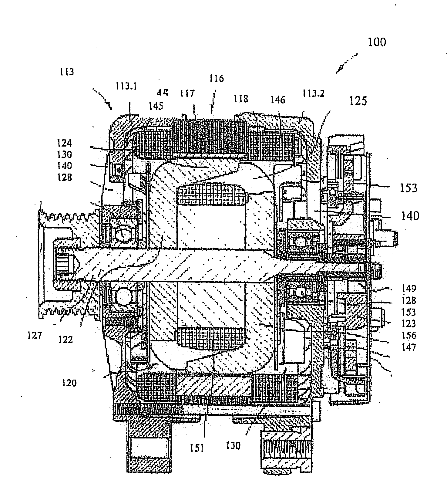
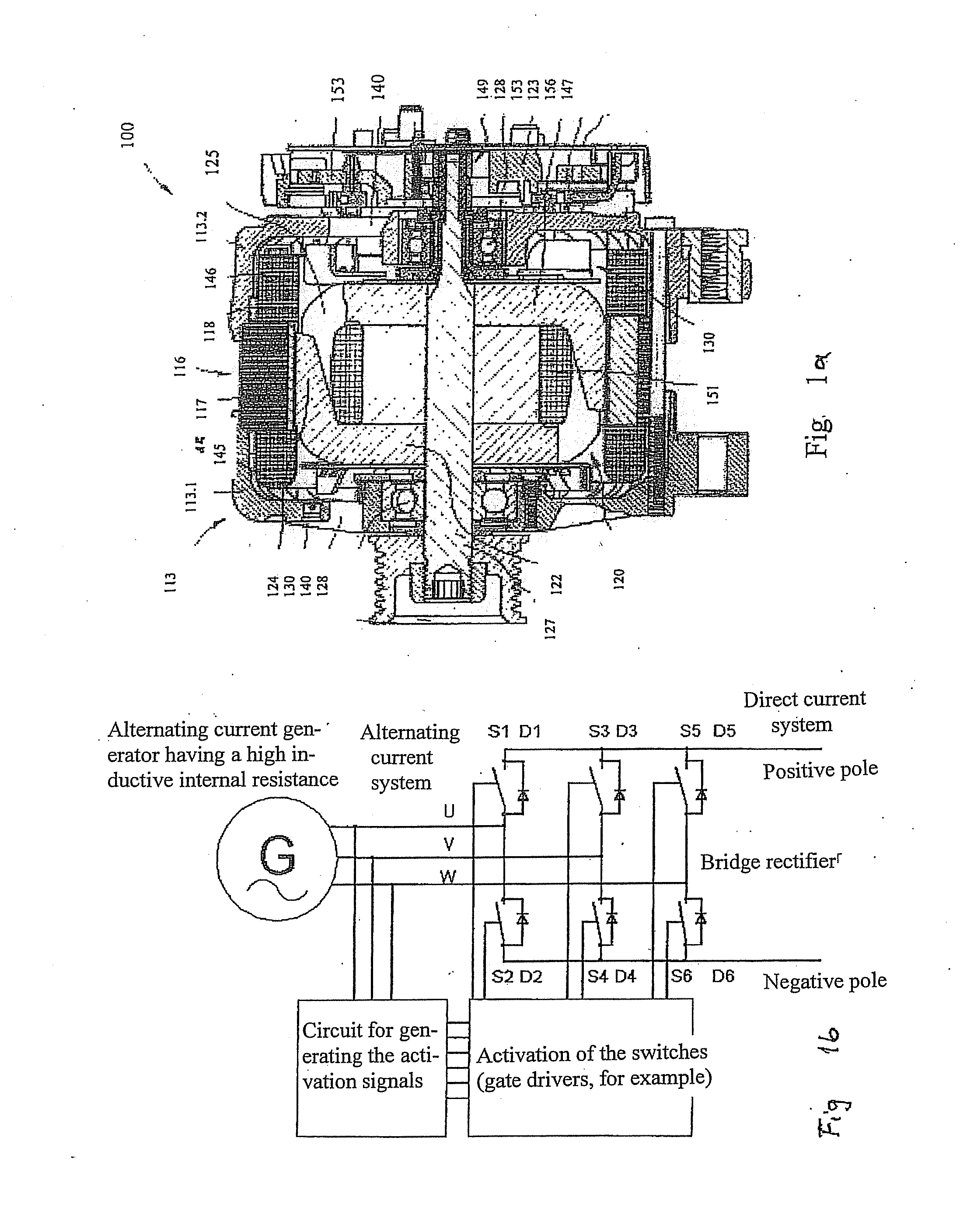
[0019]FIG. 1a illustrates a sectional view of an engine alternating current generator 100 for motor vehicles. This engine alternating current generator has, among other elements, a two-part housing 113 composed of a first end shield 113.1 and a second end shield 113.2. End shield 113.1 and end shield 113.2 accommodate a stator 116 having an annular ring-shaped core stack 117 which has inwardly open and axially extending grooves 119 in which a stator winding 118 is inserted. The radially inwardly directed surface of ring-shaped stator 116 encloses an electromagnetically excited rotor 120 which is designed as a claw pole rotor. Rotor 120 is composed, among other elements, of two claw pole plates 122 and 123, on the outer periphery of which claw pole fingers 124 and 125 are situated which in each case extend in the axial direction. Both claw pole plates 122 and 123 are situated in rotor 120 in such a way that their claw pole fingers 124, 125 which extend in the axial direction alternat...


PUM


Abstract

A rectifier bridge circuit is described for rectifying the phase voltage generated by a generator, including a positive half-bridge having multiple rectifier elements and a negative half-bridge having multiple rectifier elements. The rectifier elements each have a controllable switch having a diode connected in parallel. A control circuit is provided for switching the switches on and off. The switch-on time tswitch on setpoint and/or the switch-off time tswitch off setpoint of the switch is/are computed based on a characteristic map or a mathematical function.

Description

FIELD OF THE INVENTION[0001]The present invention relates to a rectifier bridge circuit for rectifying the phase voltages generated by a generator for activating rectifier elements.BACKGROUND INFORMATION[0002]Rectifiers are used to convert an alternating voltage into a direct-current voltage. Known rectifiers are usually installed in bridge circuits having multiple diodes as rectifier elements. Common designs are so-called half-bridge or full-bridge rectifiers. In addition, motor vehicle alternating current generators generally include a bridge rectifier for supplying the vehicle electrical system with direct-current voltage. The rectifier has a power loss which is specified by the resistance of the diodes and the output current. This power loss may be reduced only slightly by using circuitry measures such as connecting multiple diodes for each phase in parallel, for example. It is therefore known to replace the rectifier diodes with active switches, for example MOSFET transistors, ...

Claims


Application Information

Patent Timeline
Patent Type & Authority Applications(United States)
IPC IPC(8): H02M7/217
CPCY02B70/1408H02M7/219H02M7/162Y02B70/10H02M7/2195
Inventor WOLF, GERTMEHRINGER, PAULREUTLINGER, KURTWALTER, GERHARD
Owner ROBERT BOSCH GMBH
Why Eureka
Try Eureka