Brake hydraulic pressure control apparatus for vehicle

a hydraulic pressure control and brake technology, applied in the direction of tank vehicles, braking systems, transportation items, etc., can solve the problems of deteriorating seal performance between, difficult to etc., and achieve excellent effects, reduce the number of screws, and reduce the size of the base member

Active Publication Date: 2011-11-03
HITACHI ASTEMO LTD
View PDF6 Cites 3 Cited by
  • Summary
  • Abstract
  • Description
  • Claims
  • Application Information

AI Technical Summary

Benefits of technology

[0048]According to this structure, the present control apparatus can be fixed in a well balanced manner with a reduced number of screws.
[0049]According to a first aspect of the brake hydraulic pressure control apparatus for a vehicle of the invention, there can be obtained the effect that the base member can be reduced in size.
[0050]According to a second aspect of the brake hydraulic pressure control apparatus for a vehicle of the invention, there can be obtained the excellent effects that the deformation of the control housing can be prevented and the seal performance between the base member and control housing can be prevented against deterioration.

Problems solved by technology

This puts restrictions on the pipe line and layout of the interior portions of the base member, which makes it difficult to reduce the size of the base member.
This creates a clearance between the base member and control housing, resulting in the deteriorated seal performance between them.

Method used


Image

  • Brake hydraulic pressure control apparatus for vehicle
  • Brake hydraulic pressure control apparatus for vehicle
  • Brake hydraulic pressure control apparatus for vehicle

Examples


Embodiment Construction

)

[0061]Now, description will be given below specifically of an embodiment for carrying out the invention with reference to the accompanying drawings. Firstly, description will be given of the whole structure of a brake hydraulic pressure control apparatus for a vehicle according to the present embodiment.

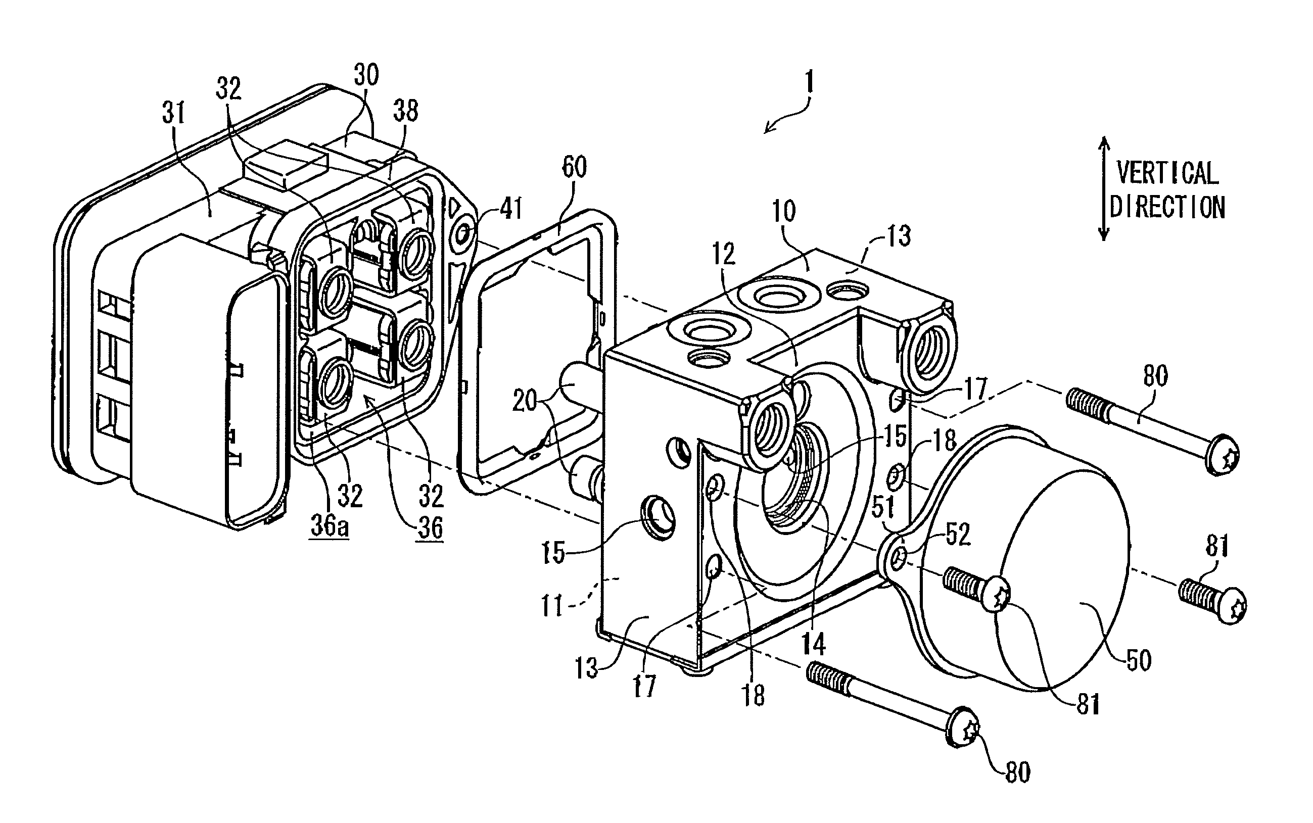
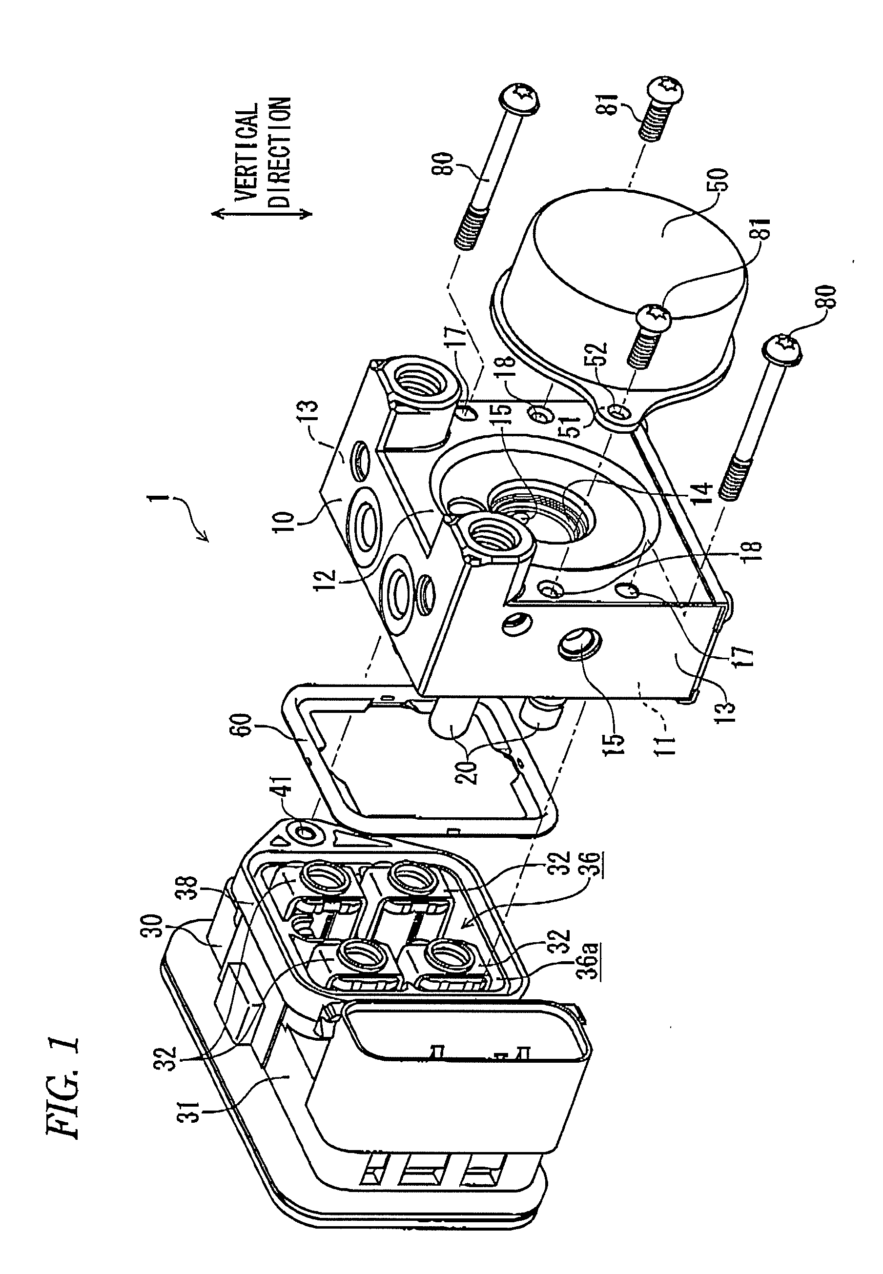
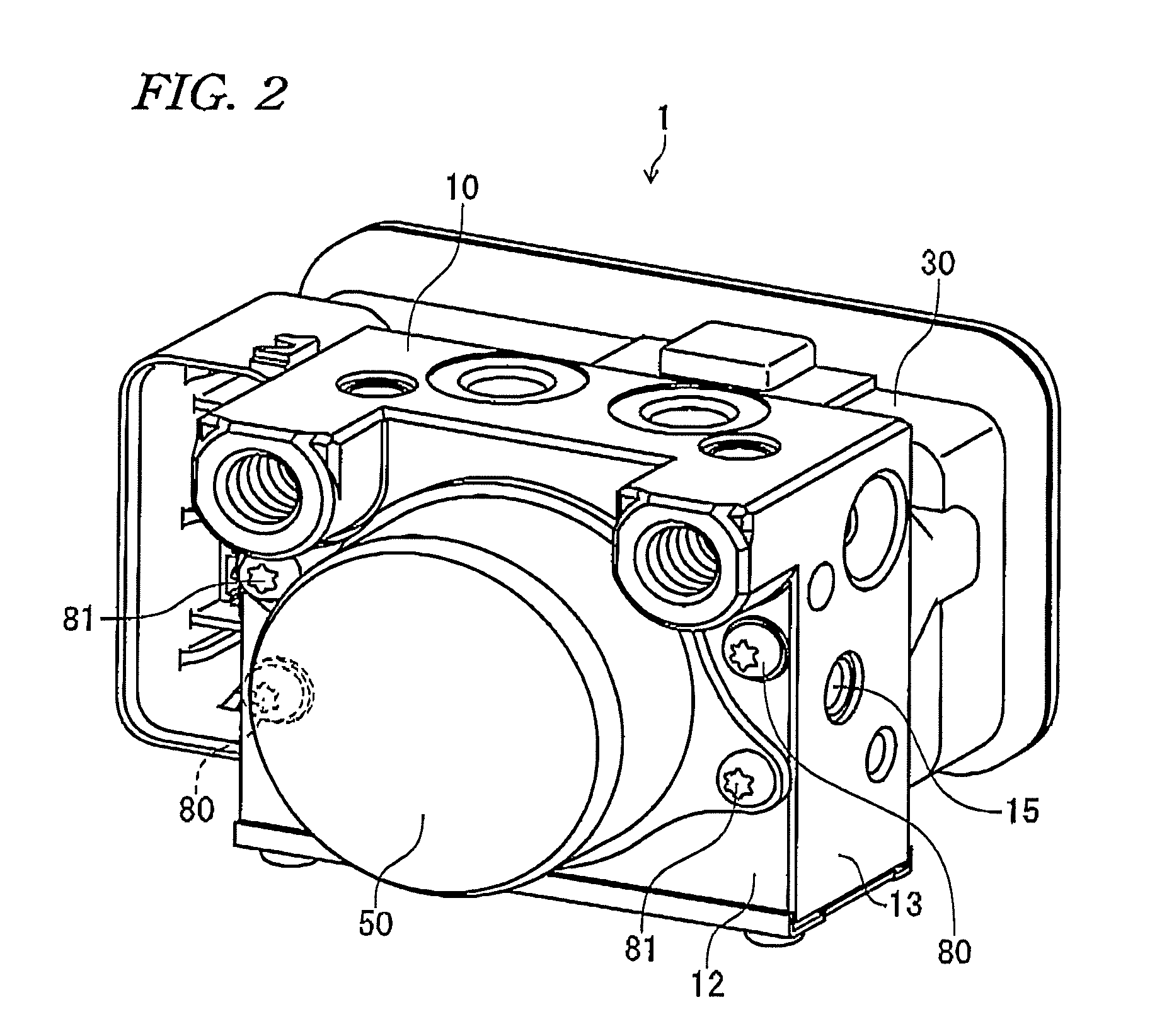
[0062]As shown in FIGS. 1 and 2, the brake hydraulic pressure control apparatus for a vehicle 1 (hereinafter, referred to as a brake hydraulic pressure control apparatus) according to the present embodiment includes a base member 10, electromagnetic valves 20 respectively provided on one face 11 of the base member 10, a control housing 30 mounted on one face 11 of the base member 10, and a motor 50 provided on a back face (the face on the rear side of one face 11) 12 of the base member 10 which is located on the opposite side of one face 11. Between one face 11 of the base member 10 and control housing 30, there is interposed a seal member (see FIG. 1).

[0063]As shown in FIG. 1, the ...


PUM


Abstract

A brake hydraulic pressure control apparatus for a vehicle includes: a base member; a control housing including a storage space for storing an electromagnetic valve on one face of the base member and a coil assembly; and a pump driving motor on a back face of the base member. The base member are provided with: two housing mounting penetration holes through which housing mounting screws for fixing the control housing are to be inserted; two motor mounting holes into which motor mounting screws for fixing the motor are to be inserted; and a rotation shaft storage hole into which a rotation shaft of the motor is to be stored, wherein the housing mounting penetration holes and the motor mounting holes are respectively disposed point-symmetrically with respect to the center of the rotation shaft storage hole.

Description

CROSS REFERENCE TO RELATED APPLICATION(S)[0001]This application claims the benefit of priority from Japanese Patent Application No. 2010-102878 filed on Apr. 28, 2010, and Japanese Patent Application No. 2010-102877 filed on Apr. 28, 2010, the disclosure of which is incorporated herein by reference in its entirety.BACKGROUND[0002]1. Field[0003]An aspect of the present application relates to a brake hydraulic pressure control apparatus fox a vehicle.[0004]2. Description of the Related Art[0005]As a brake hydraulic pressure control apparatus for a vehicle, there is known an apparatus as shown in JP-A-2009-6855. In the brake hydraulic pressure control apparatus for a vehicle disclosed in JP-A-2009-6855, there is formed a housing mounting hole in a face of a housing apparatus which is disposed opposed to a base member, and also, there is formed a housing mounting penetration hole in the base member. And, a housing mounting screw is inserted into the housing mounting penetration hole fro...

Claims


Application Information

Patent Timeline
Patent Type & Authority Applications(United States)
IPC IPC(8): B60T17/02
CPCB60T17/02B60T8/368Y10T137/6855
Inventor KODAMA, TAKURO
Owner HITACHI ASTEMO LTD
Why Eureka
Try Eureka