Light guide, surface light source device, and liquid crystal display device

a surface light source and light guide technology, applied in the direction of planar/plate-like light guides, lighting and heating apparatus, instruments, etc., can solve the problems of increasing cost, reducing the uniformity of luminance of illumination devices, and thinner displays, so as to reduce the number of components, improve the uniformity of luminance, and reduce the effect of cos

Inactive Publication Date: 2011-11-03
SHARP KK
View PDF7 Cites 40 Cited by
  • Summary
  • Abstract
  • Description
  • Claims
  • Application Information

AI Technical Summary

Benefits of technology

[0042]As described above, a light guide of the present invention includes: a main body of a light guide plate, which main body has a light incident plane and a light exit plane; and at least one distance maintaining section for maintaining a distance between the light exit plane and an optical member for receiving light emitted from the light exit plane, the at least one distance maintaining section being provided on the light exit plane, the optical member being placed to face the light exit plane, the at least one distance maintaining section (i) being provided to extend from the light exit plane to the optical member, (ii) having a length of not less than 0.3 mm but not more than 50 mm in a direction in which the light exit plane and the optical member are connected to each other via the at least one distance maintaining section, and (iii) being provided integral with the main body of the light guide plate.
[0043]Therefore, the light guide of the present invention (i) is excellent in luminance uniformity and (ii) can have a reduction in the number of components and a reduction in cost.

Problems solved by technology

This is an obstacle to make a further thinner display.
In this case, however, the illumination device has a reduction in luminance uniformity.
The increase in the number of light sources leads to an increase in cost.
However, in a case where an optical member is merely provided between the light guide and the liquid crystal display panel, it is impossible to prevent generation of dark lines and bright lines in separation sections between neighboring individual light guides.
This causes the illumination device to be poor in luminance uniformity.

Method used


Image

  • Light guide, surface light source device, and liquid crystal display device
  • Light guide, surface light source device, and liquid crystal display device
  • Light guide, surface light source device, and liquid crystal display device

Examples


embodiment 1

[0059]One embodiment of the present invention is described below with reference to FIGS. 1 through 9. Note that the present invention is not limited to this, and descriptions as to a size of, a material of, a shape of, and a relative arrangement of each of components described in the present specification are not intended to limit the scope of the present invention but are merely described as examples of the present invention, unless otherwise noted. Note that in the present specification, an expression of “A-B” stands for a range of “not less than A but not more than B”.

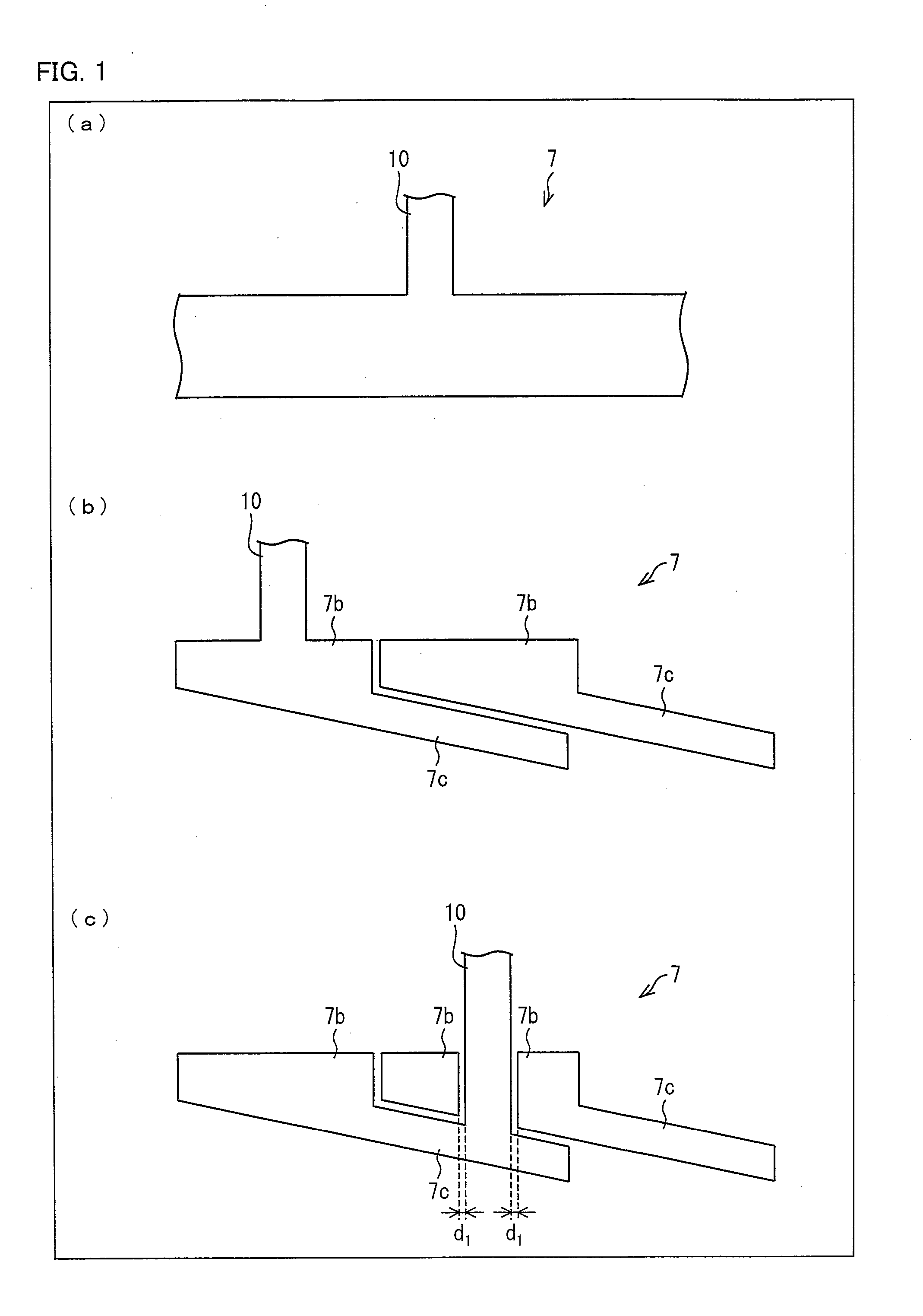
[0060]Each of (a) through (c) of FIG. 1 is a cross-sectional view schematically illustrating an arrangement of a light guide 7 of the present embodiment.

[0061]Specifically, (a) of FIG. 1 is a cross-sectional view illustrating the light guide 7 that includes (i) a main body of a light guide plate (a part of the light guide other than a distance maintaining section 10), which main body has a light incident plane and a...

embodiment 2

[0115]Another embodiment of a liquid crystal display device of the present invention is described below with reference to FIGS. 10 through 13. Note that members having the same functions as those of the members explained with drawings in Embodiment 1 are indicated with the same signs as those in Embodiment 1 for convenience. Their explanations are therefore omitted here.

[0116]According to Embodiment 1, a tandem-type backlight is explained. The present embodiment deals a tile-type backlight having an arrangement in which a plurality of light guides are arranged on the same plane but they do not overlap each other.

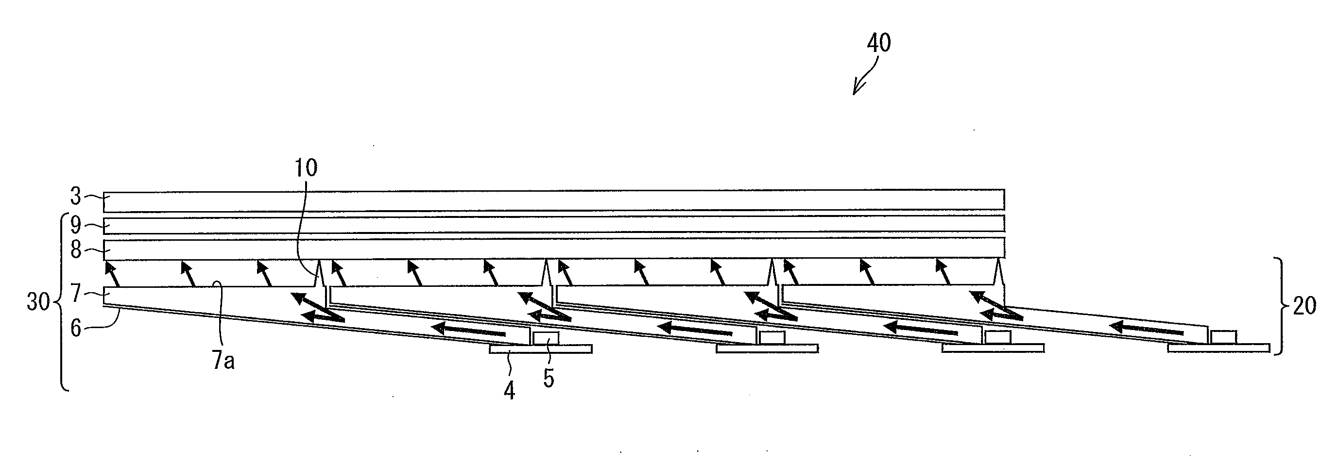
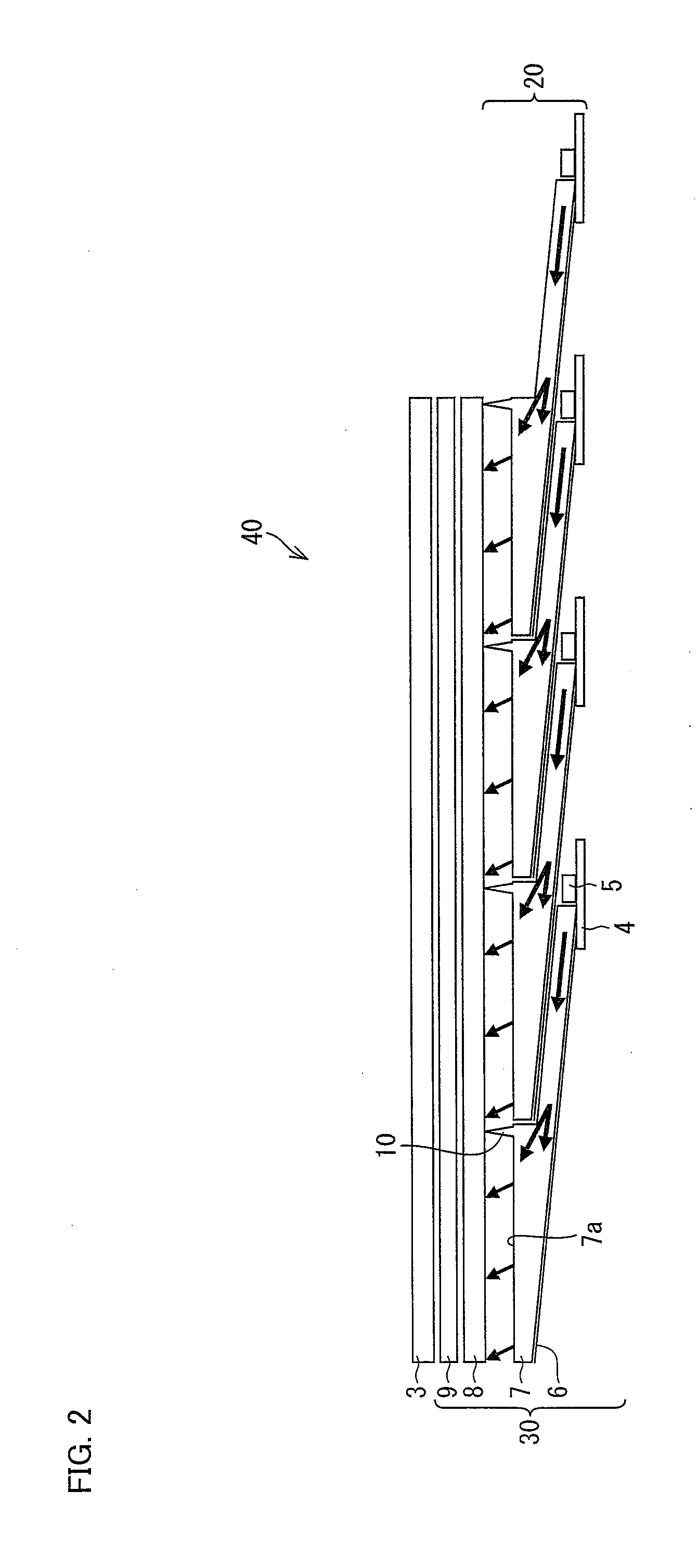
[0117]FIG. 10 is a cross-sectional view schematically illustrating an arrangement of a liquid crystal display device of the present embodiment. The liquid crystal display device 70 includes a surface light source device 60 and a liquid crystal display panel 3 which is provided to face the surface light source device 60. Note that, in the present specification, the surface li...


PUM

PropertyMeasurementUnit
lengthaaaaaaaaaa
lengthaaaaaaaaaa
angleaaaaaaaaaa

Abstract

A light guide of the present invention is excellent in luminance uniformity and can have a reduction in the number of components and a reduction in production cost. The light guide of the present invention includes a main body of a light guide plate having a light incident plane and a light exit plane, and a distance maintaining section (10) for maintaining a distance between the light exit plane and an optical member for receiving light emitted from the light exit plane, the distance maintaining section (10) being provided on the light exit plane, the optical member being placed to face the light exit plane, and the distance maintaining section (10) (i) extends from the light exit plane to the optical member, (ii) has a length of not less than 0.3 mm but not more than 50 mm in a direction in which the light exit plane and the optical member are connected to each other via the distance maintaining section (10), and (iii) is provided integral with the main body of the light guide plate.

Description

TECHNICAL FIELD[0001]The present invention relates to a light guide, a surface light source device employing the light guide, and a liquid crystal display device employing the light guide. More specifically, the present invention relates to a light guide which (i) is excellent in luminance uniformity and (ii) can have a reduction in the number of components and a reduction in production cost, a surface light source which (a) employs the light guide and (b) is used as a backlight of a liquid crystal display device or the like, and a liquid crystal display device employing the surface light source device.BACKGROUND ART[0002]These days, cathode ray tube (CRT) devices are rapidly being replaced with liquid crystal display devices. Liquid crystal display devices have advantages of low power consumption, a thin and light-weight body, and other advantages, and are therefore widely used in various devices, such as a liquid crystal television, a monitor, and a mobile phone. One of ways to fu...

Claims


Application Information

Patent Timeline
Patent Type & Authority Applications(United States)
IPC IPC(8): G02F1/13357F21V7/22
CPCG02B6/0028G02B6/0046G02B6/0078G02F1/133615G02B6/0088G02F1/133608G02B6/008
Inventor SHIMIZU, TAKAHARU
Owner SHARP KK
Why Eureka
Try Eureka