Video interpolation

a video interpolation and video technology, applied in the field of motion compensation video interpolation systems, can solve the problems of significant visual artefacts in interpolated frames, poor motion vectors may arise, etc., and achieve the effect of reducing the visibility of artefacts

Active Publication Date: 2011-11-03
IMAGINATION TECH LTD
View PDF10 Cites 15 Cited by
  • Summary
  • Abstract
  • Description
  • Claims
  • Application Information

AI Technical Summary

Benefits of technology

[0019]Preferred embodiments of the present invention provide apparatus and methods associated with reducing the visibility of artefacts in motion compensated

Problems solved by technology

In situations where the motion estimator performs badly, and produces non-true motion vectors, interpolation using these poor vectors causes artefacts.
Poor motion vectors may arise due to complex or erratic motion, objects being occluded/revealed between input frame

Method used


Image

  • Video interpolation
  • Video interpolation
  • Video interpolation

Examples


Embodiment Construction

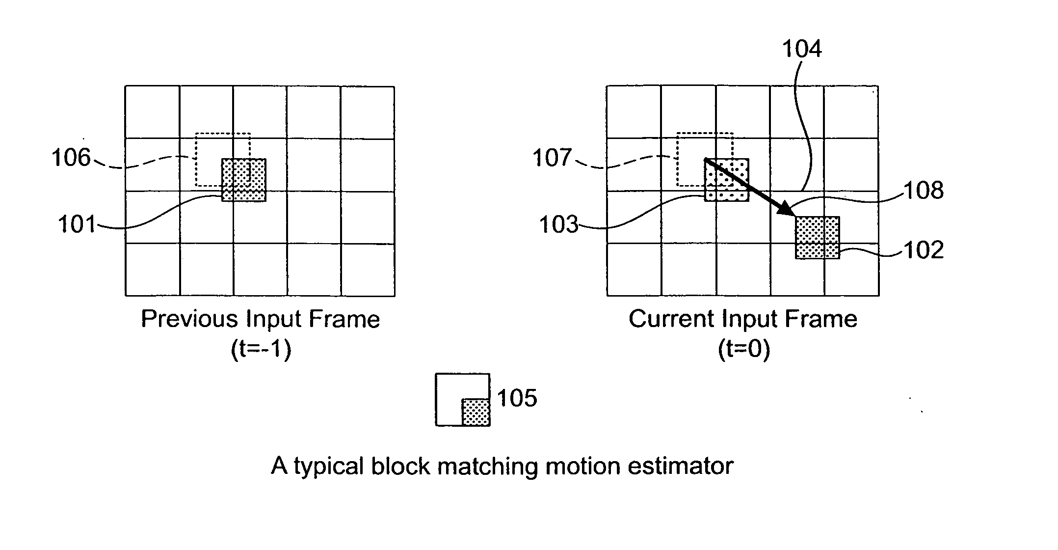
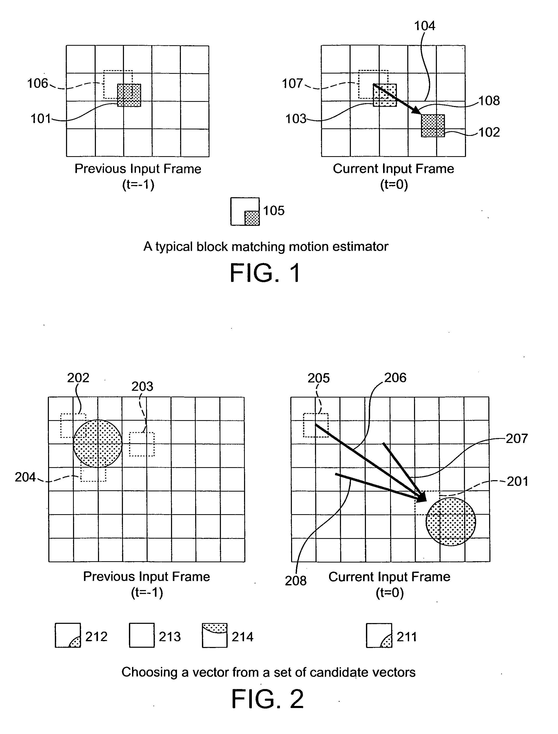
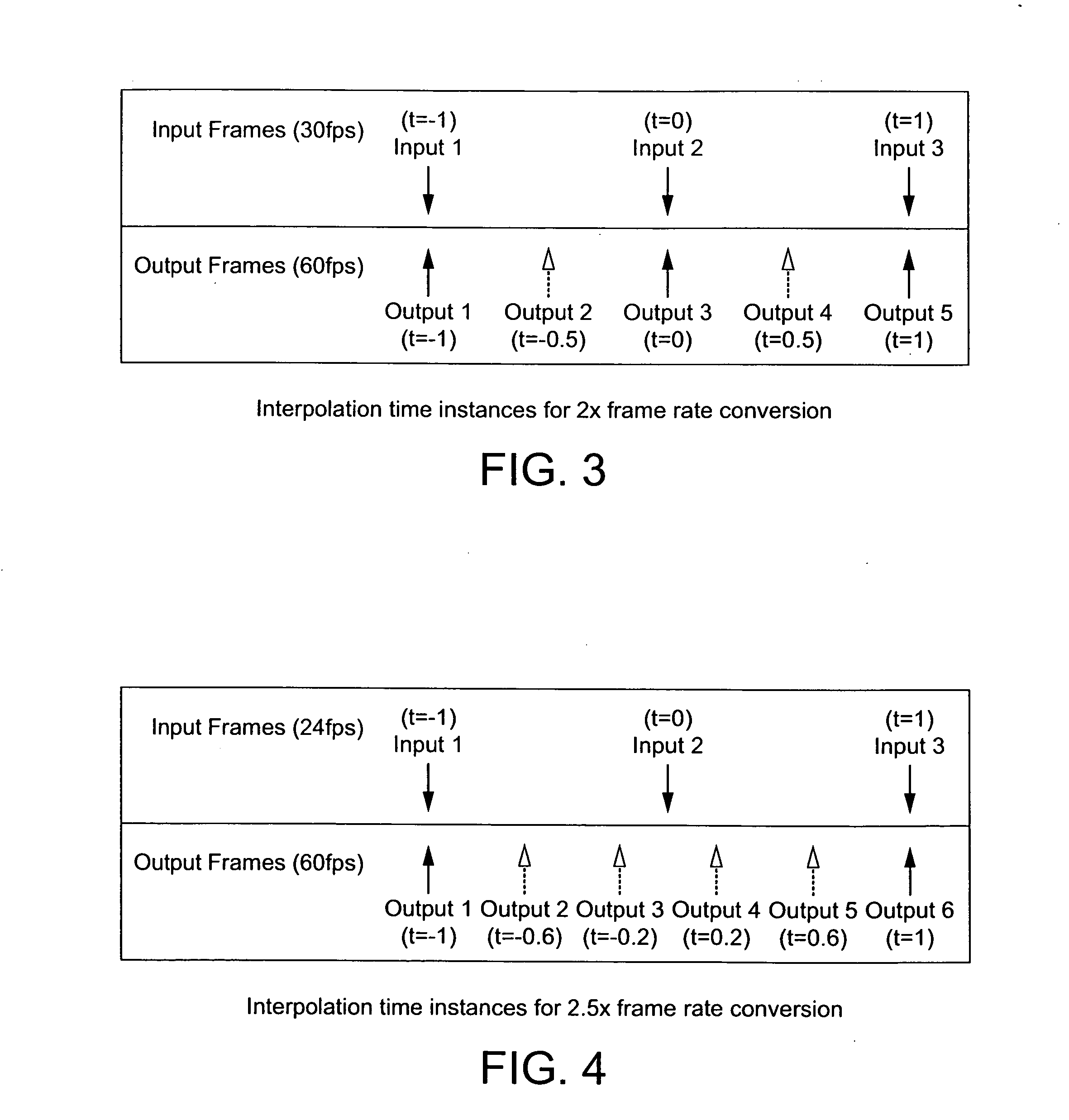
[0037]Embodiments of this invention provide a modification to motion compensated frame interpolation systems that is capable of reducing the visibility of artefacts in interpolated frames. In a conventional motion compensated frame interpolation system, the time instance at which an output frame is output in the sequence is used to determine the position of the objects in the interpolated scene. It is proposed that while an interpolated frame should still be output at the time instance at which it is required (the “ideal time”), a second “working time instance” may be used to assist with calculation of the position of objects in the screen. Conveniently, the working time instance may be defined as the ideal time instance modified by a “working scale factor”. This brings the time instance at which the frame is interpolated closer to that of an input frame. This should reduce the effect of any erratic motion vectors and provide an output with fewer artefacts which can then be used at ...


PUM


Abstract

A method and apparatus are provided for motion compensated video interpolation. Each field or frame in a sequence of video images is subdivided into a plurality of blocks and a motion vector field is derived using block matching for a current video field using data matched to a previous video field or frame. A first time instance is determined at which an interpolated block is to be displayed and a second time instance is determined at which a corresponding interpolated block is to be created. Video data for each block is interpolated at its second time instance for each block and is then output for display at the first time instance.

Description

FIELD OF THE INVENTION[0001]This invention relates to motion compensated video interpolation systems, and in particular to methods and apparatus associated with reducing the visibility of artefacts in motion compensated video interpolation.BACKGROUND TO THE INVENTION[0002]Video sequences typically comprise a series of non interlaced frames of video data, or a series of interlaced fields of video data. Interlaced sequences are produced by fields which carry data on alternate lines of a display, such that a first field will carry data for alternate lines, and a second field will carry data for the missing lines. The fields are thus spaced both temporally and spatially. Every alternate field in a sequence will carry data at the same spatial locations. A pair of interlaced field may be referred to as a frame and a non-interlaced field may also be referred to as a frame. Embodiment of this invention will be described in terms of a non-interlaced system, but the invention is equally appli...

Claims


Application Information

Patent Timeline
IPC IPC(8): H04N7/26
CPCH04N7/014H04N7/0127
Inventor MORPHET, STEPHENFISHWICK, STEVEN
Owner IMAGINATION TECH LTD
Why Eureka
Try Eureka