
Conveyor oven apparatus and method

a technology of conveying oven and oven chamber, which is applied in the field of conveying oven apparatus and method, can solve the problems of relatively cold uncooked food, and achieve the effect of reducing the internal temperature of the heated tunnel

Active Publication Date: 2011-11-03
MIDDLEBY CORPORATION
View PDF28 Cites 55 Cited by
  • Summary
  • Abstract
  • Description
  • Claims
  • Application Information

AI Technical Summary

Benefits of technology

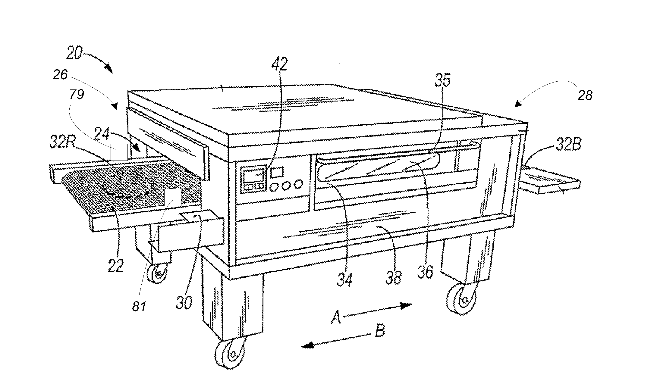
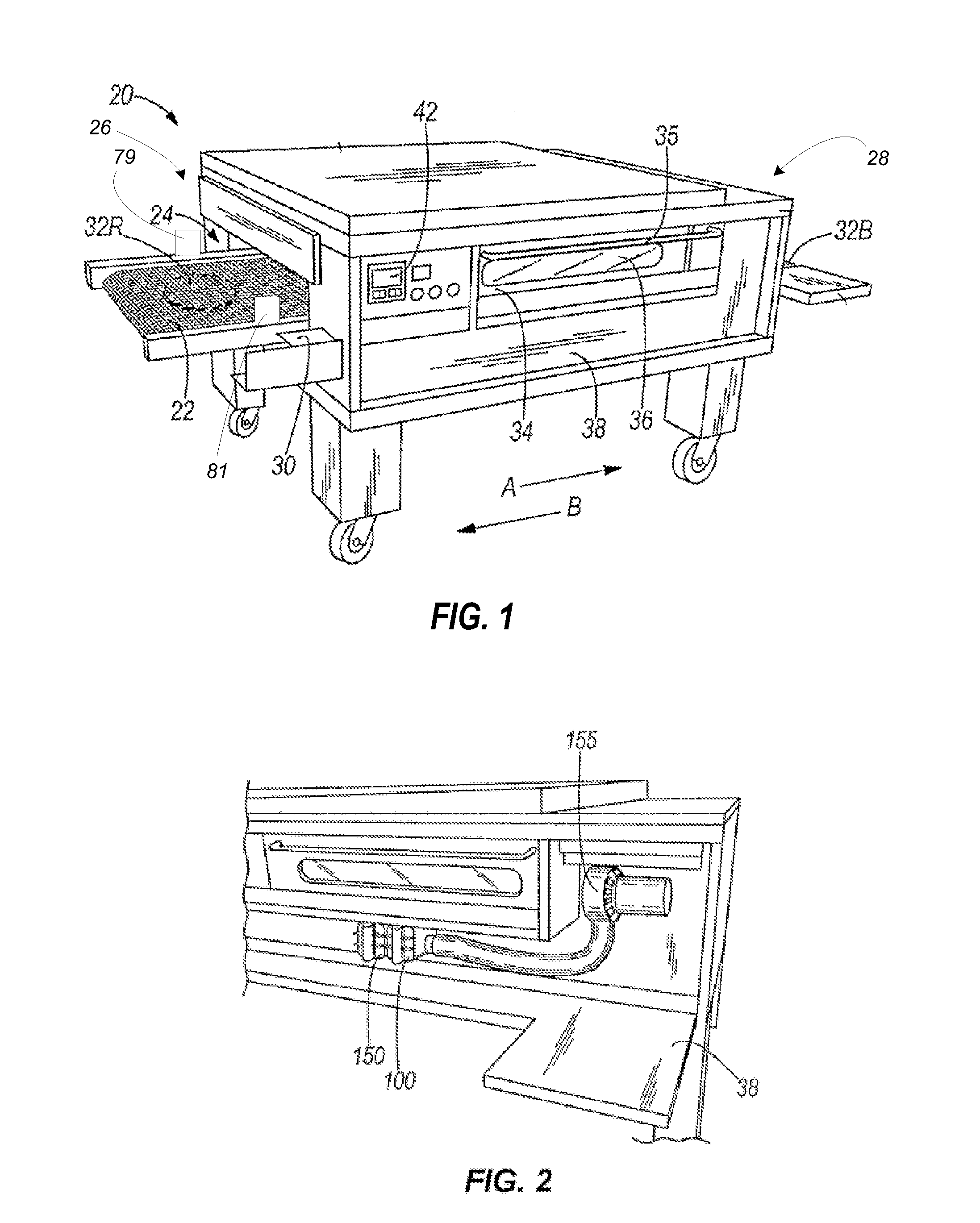
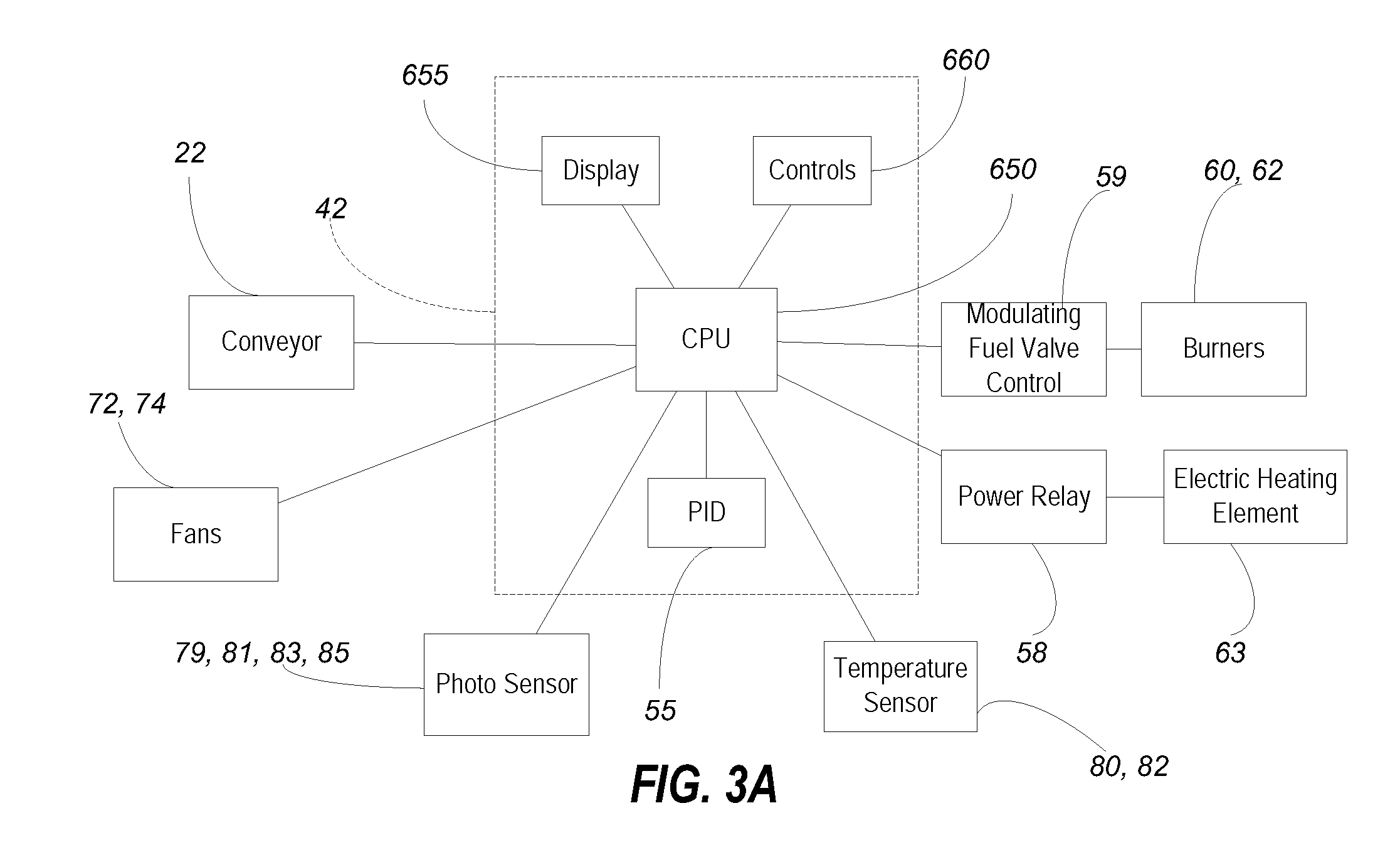
[0018]Some embodiments provide an oven with a heated tunnel, a door providing access to the heated tunnel, a heating element, a sensor, and a controller. The sensor is configured to detect when the door is open and when the door is closed. The controller is configured to adjust the internal temperature of the heated tunnel toward a set-point temperature by using a PID control to control the heating element. When the sensor detects that the door is open, the controller increases the output of the heating element.
[0019]Another embodiment provides a method of controlling the temperature of a conveyor oven having a heated tunnel with an entrance and an exit, a conveyor, a heating element, and a controller. The method includes monitoring with a sensor the presence of food items on the conveyor before the food items pass beyond the entrance of the heated tunnel into the heated tunnel; monitoring open and closed states of a door configured to provide access to the heated tunnel of the conveyor oven; and controlling the heating element with the controller. The method also includes configuring the controller to adjust an internal temperature of the heated tunnel toward a set-point temperature by controlling the thermal output of the heating element. The controller is also configured to generate a signal to increase the thermal output of the heating element for a first predetermined amount of time after the sensor detects a first food item in anticipation of the first food item causing a decrease in the internal temperature of the heated tunnel. The controller also generates a signal to increase the thermal output of the heating element for the first predetermined amount of time after the sensor detects a second food item if a second predetermined amount of time elapses between the detection of the first food item and the detection of the second food item, and increases the output of the heating element after the sensor detects that the door is in the open state.

Problems solved by technology

For example, uncooked food is relatively cold.

Method used


Image

  • Conveyor oven apparatus and method
  • Conveyor oven apparatus and method
  • Conveyor oven apparatus and method

Examples


Embodiment Construction

[0070]Before any embodiments of the invention are explained in detail, it is to be understood that the invention is not limited in its application to the details of construction and the arrangement of components set forth in the following description or illustrated in the following drawings. The invention is capable of other embodiments and of being practiced or of being carried out in various ways. Also, it is to be understood that the phraseology and terminology used herein is for the purpose of description and should not be regarded as limiting. The use of “including,”“comprising,” or “having” and variations thereof herein is meant to encompass the items listed thereafter and equivalents thereof as well as additional items. Unless limited otherwise, the terms “connected,”“coupled,” and “mounted” and variations thereof herein are used broadly and encompass direct and indirect connections, couplings, and mountings, and the terms “connected” and “coupled” and variations thereof are ...


PUM


Abstract

An oven with a sensor positioned to detect an event that will cause a decrease in the internal temperature of a tunnel. The oven includes a controller configured to increase the thermal output of a heating element in anticipation of the upcoming decrease in the internal temperature. In some embodiments, the oven is a conveyor over and the sensor is positioned to detect a food item approach the tunnel on a conveyor. In some embodiments, the amount of current provided to an electric heating element is increased by increasing the target temperature. In some embodiments, the amount of current provided to the electric heating element is increased by a predetermined offset.

Description

CROSS-REFERENCE TO RELATED APPLICATIONS[0001]This application claims priority to and is a Continuation-in-part of International Patent Application No. PCT / US2009 / 030727, filed Jan. 12, 2009, which is a Continuation-in-part of U.S. patent application Ser. No. 12 / 233,969, filed Sep. 19, 2008, which is a Continuation of U.S. patent application Ser. No. 11 / 526,133, filed Sep. 22, 2006, which is a Continuation of International Patent Application No. PCT / US2006 / 022304, filed Jun. 8, 2006, which is a Continuation-in-part of International Patent Application No. PCT / US2005 / 009546, filed Mar. 23, 2005, which claims the benefit of U.S. Provisional Patent Application No. 60 / 555,474, filed Mar. 23, 2004.[0002]This application also claims priority to and is a Continuation-in-part of U.S. patent application Ser. No. 12 / 233,969, filed Sep. 19, 2008, which is a Continuation of U.S. patent application Ser. No. 11 / 526,133, filed Sep. 22, 2006, which is a Continuation of International Patent Applicatio...

Claims


Application Information

Patent Timeline
Patent Type & Authority Applications(United States)
IPC IPC(8): F27B9/30A21B1/00
CPCA21B1/48A21B1/40A21B3/04
Inventor WIKER, JOHN H.PANICKER, MOHAN K.VAN CAMP, RICHARD H.CHMIOLA, THEODORE JAMES
Owner MIDDLEBY CORPORATION
Learn More