Hydraulic drive device having two pressure chambers and method for operating a hydraulic drive device having two pressure chambers

a hydraulic drive and pressure chamber technology, applied in the direction of fluid couplings, rotary clutches, servomotors, etc., can solve the problems of considerable energy loss, and achieve the effect of energy-saving hydraulic operation

Active Publication Date: 2011-11-10
VOITH PATENT GMBH
View PDF3 Cites 3 Cited by
  • Summary
  • Abstract
  • Description
  • Claims
  • Application Information

AI Technical Summary

Benefits of technology

[0004]The object of the invention is to permit an energy-saving hydraulic operation,

Problems solved by technology

In the hydraulic drive devices known hitherto from the prior art, however, the return movement of the piston is also assoc

Method used


Image

  • Hydraulic drive device having two pressure chambers and method for operating a hydraulic drive device having two pressure chambers
  • Hydraulic drive device having two pressure chambers and method for operating a hydraulic drive device having two pressure chambers
  • Hydraulic drive device having two pressure chambers and method for operating a hydraulic drive device having two pressure chambers

Examples


Embodiment Construction

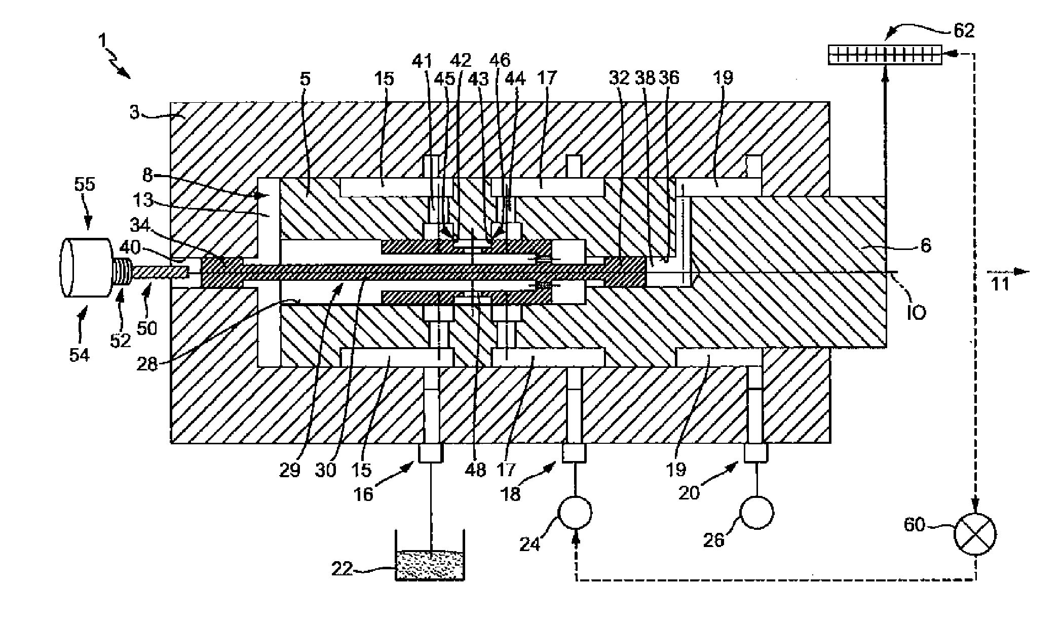
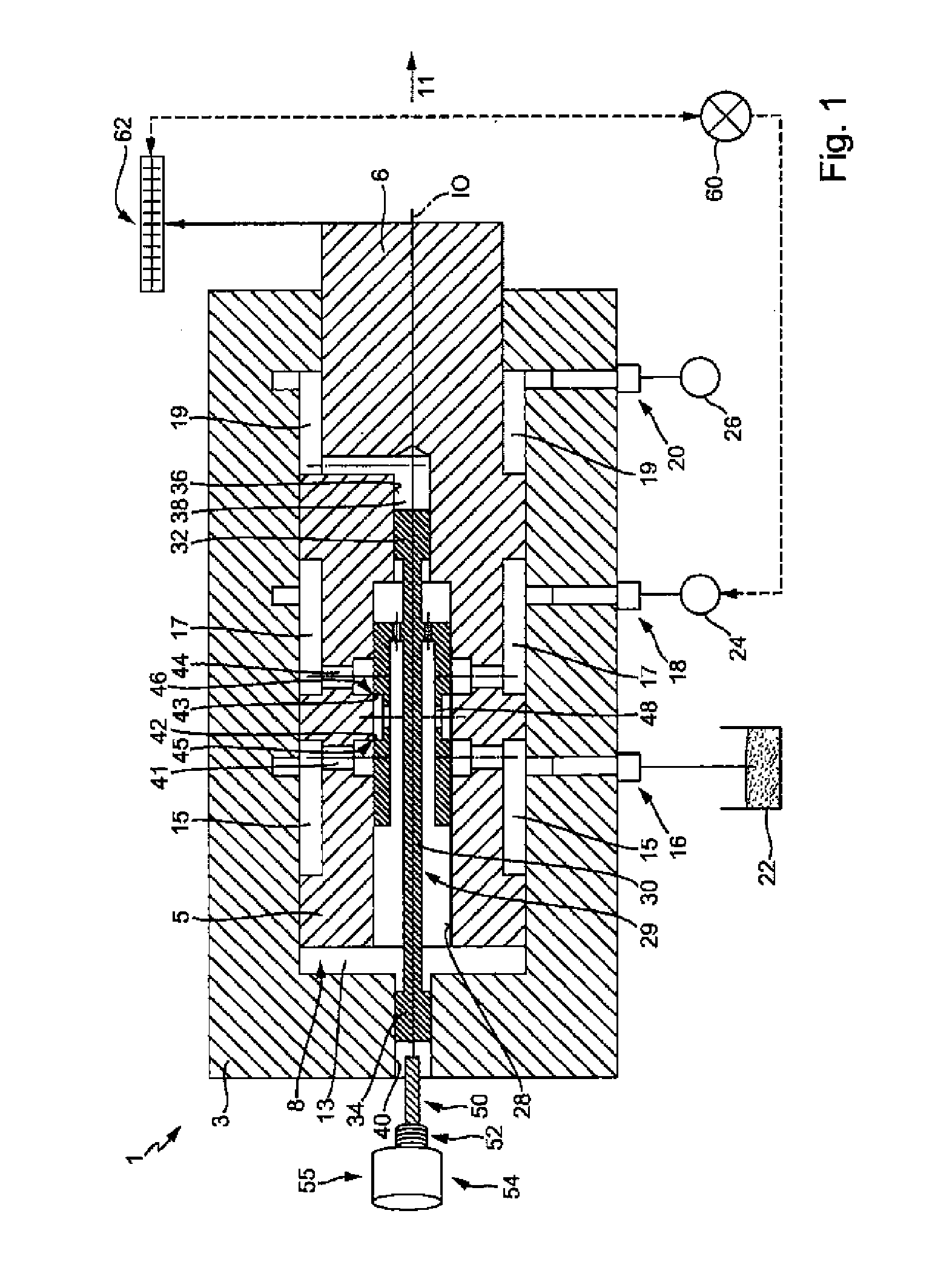
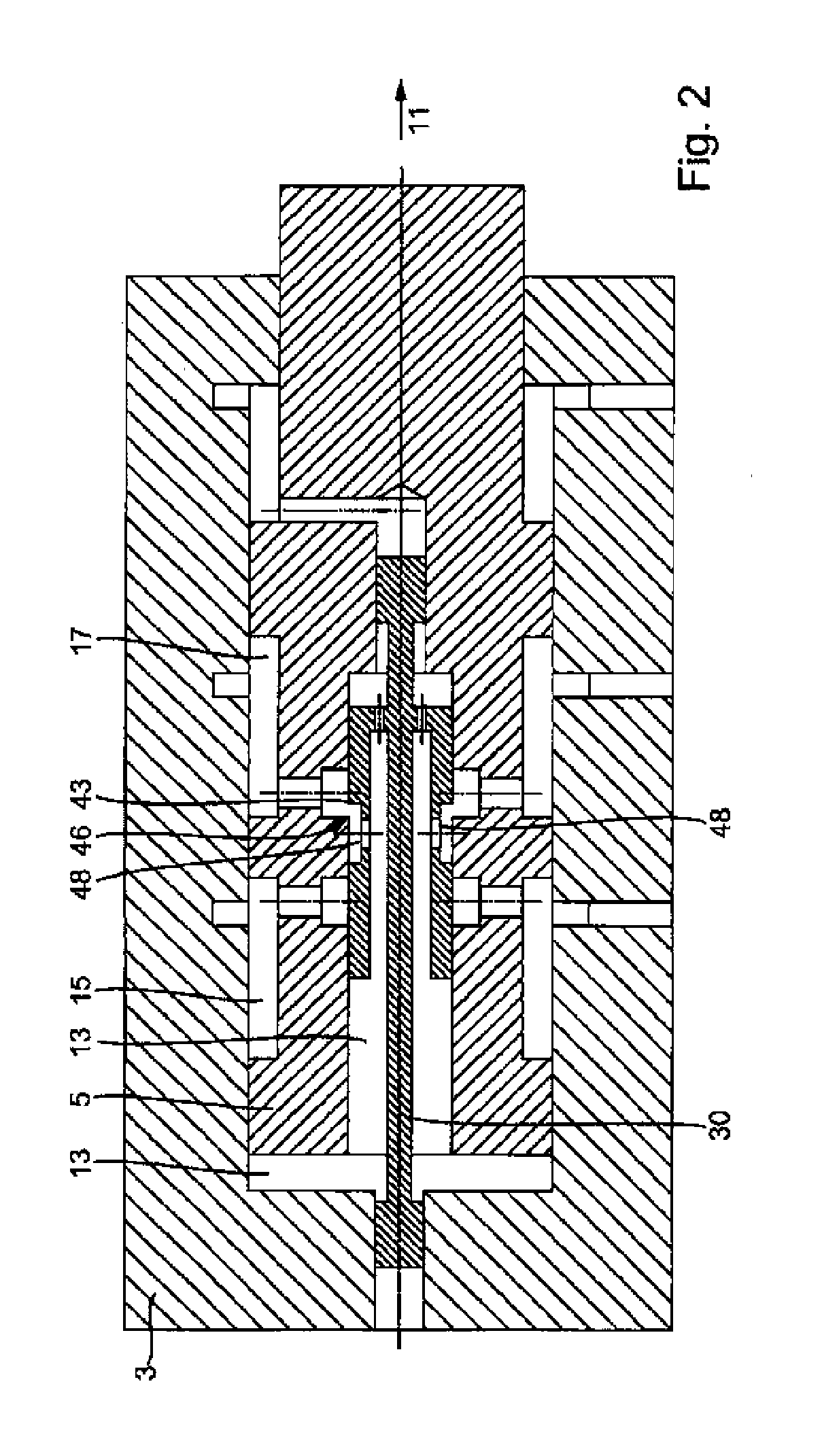
[0030]The hydraulic working device shown in FIGS. 1-3, has a cylinder 3 and a piston 5. The piston 5 is displaceably and sealingly guided in a cylinder chamber 8 along a working axis 10. The piston 5 is integrally connected to a piston rod 6, which protrudes beyond the cylinder 3 in a working direction 11. The piston rod 6 may be connected, for example, to a stamping tool (not shown) for forming a workpiece (not shown). The piston 5 defines a working pressure chamber 13, a return flow chamber 15, a high pressure chamber 17 and a low pressure chamber 19 which, for operating the device in the manner described further below, are filled with hydraulic fluid. A pressurization of the working pressure chamber 13 with hydraulic fluid thus produces a force on the piston 5 in the working direction 11, whilst a pressurization of the low pressure chamber 19 produces a force on the piston 5 counter to the working direction 11. The return flow chamber 15 is connected to a tank 22 via a tank conne...


PUM


Abstract

The invention relates to a hydraulic drive device, comprising a piston which is guided displaceably in a cylinder chamber along a working axis and adjoins a working pressure chamber that can be pressurized by hydraulic fluid, and comprising a control means that is guided in the piston at least in some sections between different control states in order to control the flow of the hydraulic fluid from a high pressure supply into the working pressure chamber to move the piston in the working direction and from the working pressure chamber to a return flow chamber, wherein the region of the piston facing away from the working pressure chamber delimits a low pressure chamber that is pressurized by a low pressure supply for hydraulic fluid during the operation of the device such that the piston is moved back against the working direction when the control means connects the working pressure chamber to the return flow chamber. The invention furthermore relates to a method for operating a hydraulic drive device.

Description

BACKGROUND OF THE INVENTION[0001]The invention relates to a hydraulic drive device comprising a piston which is displaceably guided in a cylinder chamber along a working axis, and which defines a working pressure chamber which may be pressurized by hydraulic fluid, and comprising a control means guided in the piston at least partially between various control states, for controlling the throughflow of hydraulic fluid from a high pressure supply into the working pressure chamber to move the piston in the working direction, and from the working pressure chamber to a return flow chamber. The invention further relates to a method for operating a hydraulic drive device comprising a piston which is displaceably guided in a cylinder chamber and which defines a working pressure chamber, the working pressure chamber being pressurized by hydraulic fluid to move the piston in the working direction.[0002]Hydraulic drive devices and methods of the aforementioned type are known in various embodime...

Claims


Application Information

Patent Timeline
IPC IPC(8): F15B1/26F15B1/00
CPCF15B9/09F15B15/204F15B13/0403
Inventor SCHABER, HUBERT
Owner VOITH PATENT GMBH
Why Eureka
Try Eureka