Vacuum seed meter

Inactive Publication Date: 2011-11-10
SHOUP KENNETH E MR
View PDF2 Cites 9 Cited by
  • Summary
  • Abstract
  • Description
  • Claims
  • Application Information

AI Technical Summary

Benefits of technology

[0009]As the drum is rotated through a supply of seeds to be planted, individual seeds are urged onto the apertures of the arm members and corresponding seed disk apertures, and held in place by the vacuum. A lifter mechanism is mounted with a frame and includes an end that engages at least the portion of the seed disk or drum defining the seed apertures. The seed disk or drum is rotatable relative to the end of the lifter. As the seed disk is rotated, the lifter causes the radial outward end of the arm members to be urged away from the surface of the seed disk or drum. In so doing, the seed held on the arm member is moved away from the vacuum source such that communication with the vacuum source is disrupted. The seed, lacking sufficient force to be held to the end of the arm member, is then released. The lifter may optionally include a portion that also occludes the

Problems solved by technology

In so doing, the seed held on the arm member is moved away from the vac

Method used


Image

  • Vacuum seed meter
  • Vacuum seed meter
  • Vacuum seed meter

Examples


Embodiment Construction

[0029]While particular embodiments of the present invention have been shown and described, it will be appreciated by those skilled in the art that changes, modifications and improvements may be made without departing from the true spirit and scope of the invention.

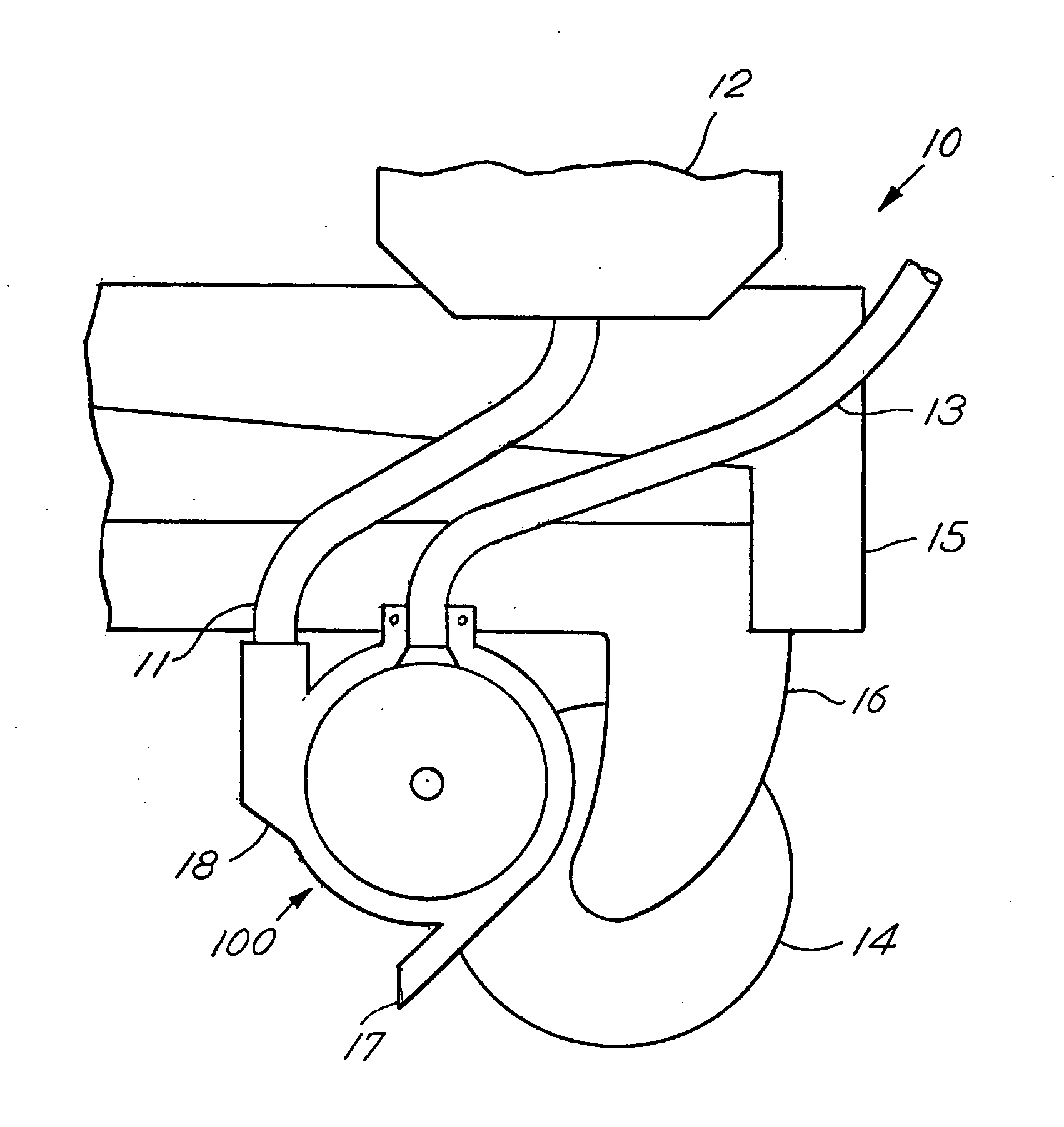
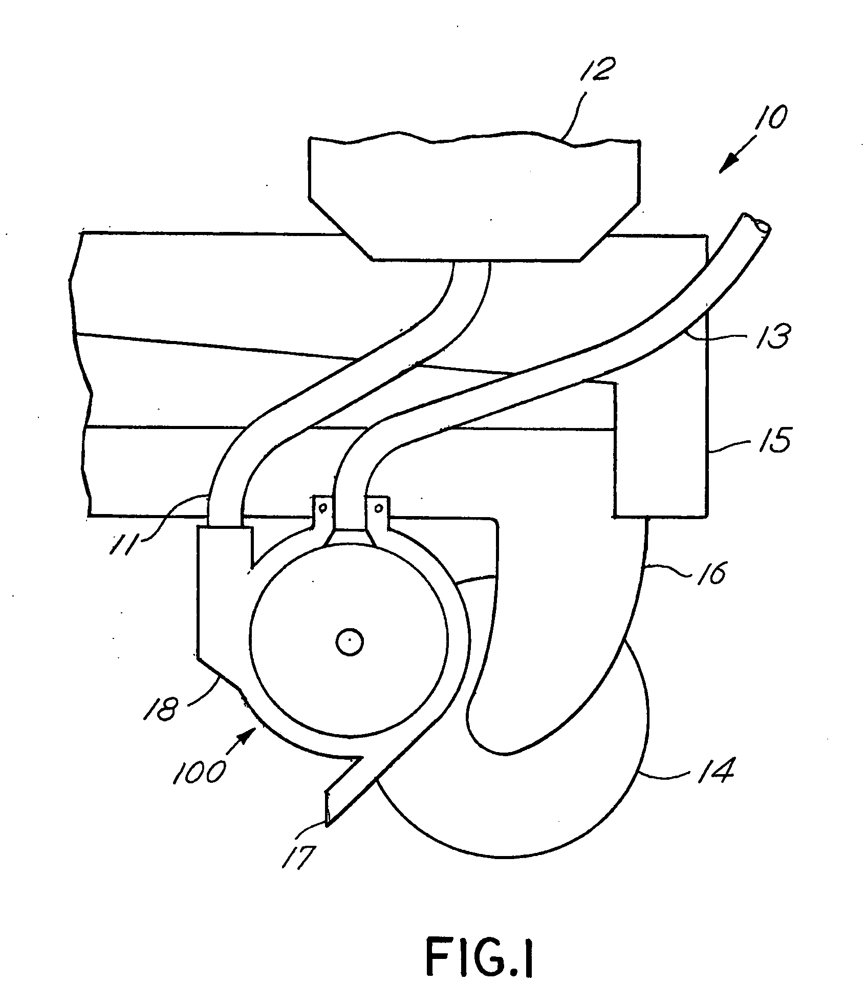
[0030]Shown in FIG. 1 is a schematic right side elevational view of planting unit 10, including vacuum seed meter disk assembly 100. Planting unit 10 includes seed hopper 12 connected to seed tube 11. Seed tube 11 is connected to seed meter disk assembly 100. Seed meter disk assembly 100 is encased within assembly cover 18. Assembly cover 18 includes seed dispensing tube 17. Connected to seed meter disk assembly 100 is vacuum tube 13. Vacuum tube 13 is connected to a vacuum source (not shown). Seed meter disk assembly 100 is mounted to subunit frame 16. Also mounted to subunit frame 16 is furrow opening disk 14. Subunit frame 16 is connected to row unit frame 15. Row unit frame 15 is connected to a tractor (not shown). As ...


PUM


Abstract

A seed meter for an agricultural seed planter, wherein the seed meter includes a rotating distributing seed disk defining a plurality of radially spaced apertures. The seed disk or drum is operatively connected to a vacuum source for creating a pressure differential between the exterior and the interior of the seed disk so as to pick up seeds for dispensing. Secured to the exterior surface of the seed disk are a plurality of arm members made from a resilient, yet rigid material, such as spring steel, which include an end portion defining an aperture that is positioned over a corresponding aperture formed about the periphery of the seed disk. As the drum is rotated through a supply of seeds, individual seeds are urged onto the apertures of the arm members and corresponding seed disk apertures, and held in place by the vacuum. A lifter mechanism mounted with a frame and including an end that engages at least the portion of the seed disk or drum defining the seed apertures causes the radial outward end of the arm members to be urged away from the surface of the seed disk as the disk is rotated relative to the end of the lifter so that the seed held on the arm member is moved away from the vacuum source and communication with the vacuum source is disrupted. The lifter may optionally include a portion that also occludes the aperture in the seed disk, thereby temporarily cutting off the vacuum force from the individual seed entirely. The lifter in conjunction with a vacuum breaker plate may also physically dislodge any seed or debris not previously removed. As the seed disk continues to rotate, the arm members are disengaged from the lifter such that the arm members are allowed to return to the position where the apertures in the arm members and seed disk are again overlaid.

Description

FIELD OF THE INVENTION[0001]The present invention generally relates to seed metering mechanisms for dispensing individual seeds at a controlled rate into a seed furrow as the seed meter is advanced above and along the furrow and, more particularly to a vacuum seed metering mechanism including an apparatus for separating the seeds from the vacuum source.BACKGROUND OF THE INVENTION[0002]Seed meters for dispensing seeds at a controlled rate into a seed furrow as the seed meter is advanced above and along the seed furrow have been in use for many years. In a conventional arrangement, a tractor is coupled with planting units with seed meters. The planting units generally include seed hoppers for the seeds to be planted or a smaller container fed from a centralized bin or large hopper, and a device for opening a furrow in the ground as the tractor is advanced across the field. A seed meter is connected to the seed hopper for dispensing individual seeds into the furrow at a controlled rate...

Claims


Application Information

Patent Timeline
IPC IPC(8): A01C7/16
CPCA01C7/046
Inventor SHOUP, KENNETH E.
Owner SHOUP KENNETH E MR
Why Eureka
Try Eureka