Motor with turbine and worm decelerator

A reduction mechanism, worm gear technology, applied in the direction of electromechanical devices, electrical components, electric components, etc., can solve the problem of affecting the output torque and life of the worm gear reduction mechanism, affecting the rotational rigidity and stability of the motor, armature pieces and commutators. Increase the diameter and other problems to achieve the effects of reducing vibration and noise, improving output torque, and improving rigidity and stability

Inactive Publication Date: 2005-03-02
胜华波集团有限公司
View PDF0 Cites 9 Cited by
  • Summary
  • Abstract
  • Description
  • Claims
  • Application Information

AI Technical Summary

Problems solved by technology

[0002] In a traditional small motor with a worm gear reduction mechanism, the shaft of the fixed armature is coaxial with the worm of the worm gear reduction mechanism connected to its transmission, and the diameter of the armature shaft is basically the same as the diameter of the worm, so that both There is a contradiction between mutual containment: when the diameter of the overall shaft is large, that is to say, when the diameters of the worm and the armature shaft are large, although the diameter of the worm is large, the contact area between the worm and the worm wheel can be increased, and the output torque and the worm gear can be increased. service life, but the corresponding armature shaft diameter is also larger at this time, resulting in a corresponding increase in the diameter of the armature plate and commutator, thereby increasing the volume of the motor
Conversely, if the diameter of the overall rod shaft is reduced, the diameter of the armature will be reduced, and the diameter of the worm will be reduced accordingly, which will affect the output torque and life of the worm gear reduction mechanism.
Moreover, the armature worm shaft of this overall structure is only at its two ends: that is, the outer end of the armature shaft and the outer end of the worm shaft are provided with support bearings, and there is no supporting point in the middle of the integral rod shaft, so the rigidity and rotation of the motor are affected. Stationarity

Method used


Image

  • Motor with turbine and worm decelerator

Examples


Embodiment Construction

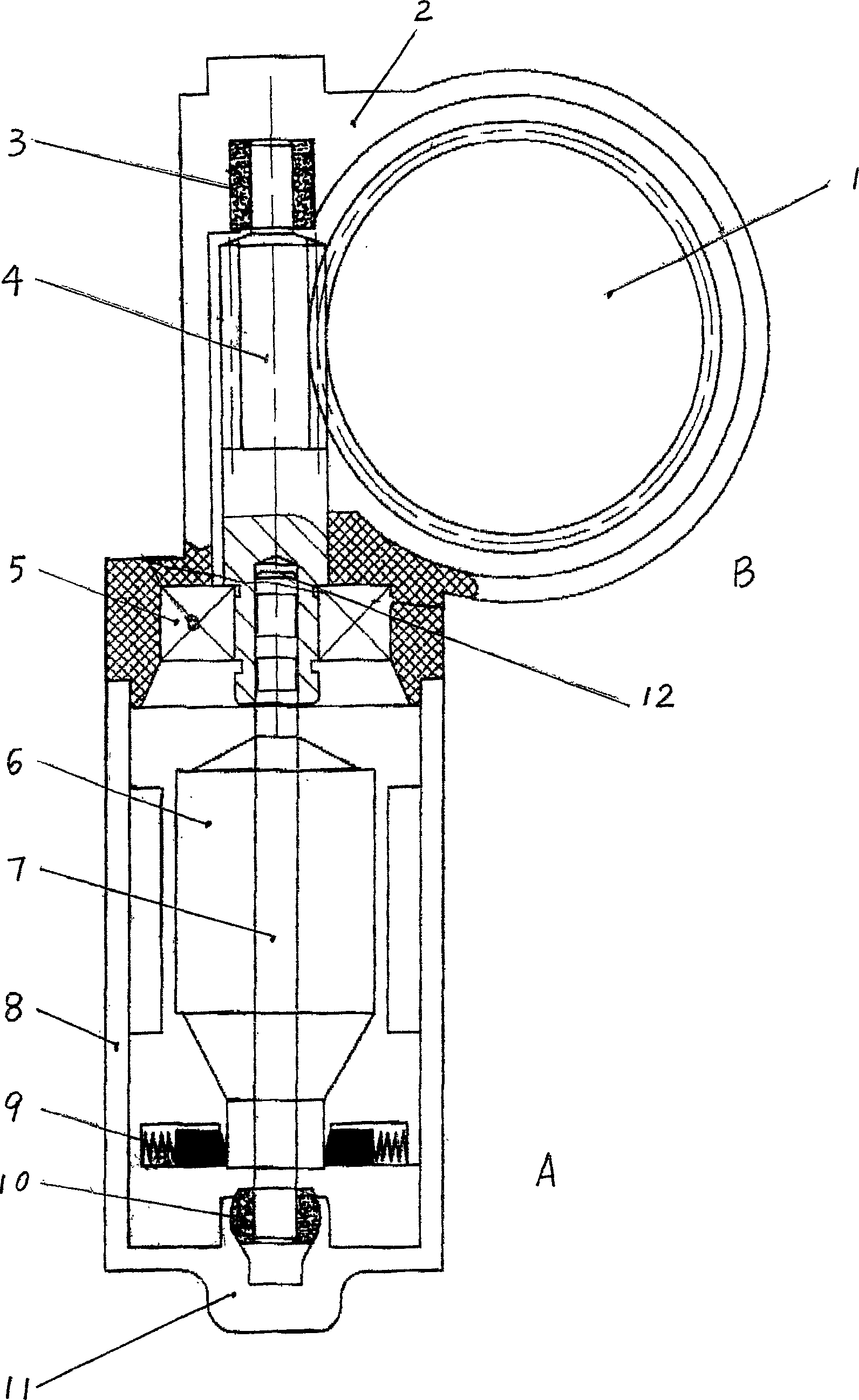
[0010] This example is a miniature motor, and the worm gear reduction device B installed in the reduction mechanism housing 2 is connected with the motor A transmission installed in the motor housing 8 .

[0011] The armature assembly 6 in the motor A is installed on the armature shaft 7, the worm 4 in the worm gear reduction mechanism B is connected to the worm gear 1, the worm 4 and the armature shaft 7 are split structures, and the armature One end of the shaft is inserted into the processing hole on the end face of the worm, and is coaxially connected with the worm through an adhesive. The armature shaft 7 has a groove 12 on the side wall of its connection with the worm. The function of this groove is to ensure There is sufficient strength when the armature shaft is bonded to the worm.

[0012] The end of the armature shaft 7 away from the worm is connected to the rear end cover 11 of the motor casing through a bearing 10, the bearing 10 is a ball bearing, the ball bearing...


PUM


Abstract

This invention relates to a kind of electric motor equiped with worm and worm-gear reducer which composed of an elecric motor and a worm / worm-gear reducing mechanism. The pivot of electric motor and worm of the reduce are combined into a single one. On the outer ends of said pivot and worm are equipped, respectively, bearings. It is characterised by that the diameter of the worm is 1.5 times of the diameter of pivot of electric motor. The other end near the pivot is equipped with another bearing. This invention electric motor is compacted with its size while gives out greater output force moment, which increased rigidity and stability and lowered noise and vibration.

Description

technical field [0001] The invention belongs to a small motor with a worm gear reduction mechanism. Background technique [0002] In a traditional small motor with a worm gear reduction mechanism, the shaft of the fixed armature is coaxial with the worm of the worm gear reduction mechanism connected to its transmission, and the diameter of the armature shaft is basically the same as that of the worm, so that both There is a contradiction between mutual containment: the overall diameter of the rod shaft is large, that is to say, when the diameters of the worm and the armature shaft are large, although the large diameter of the worm can increase the contact area between the worm and the worm wheel, increase the output torque and the worm wheel. service life, but the corresponding armature shaft diameter is also larger at this time, resulting in a corresponding increase in the diameter of the armature plate and commutator, thereby increasing the volume of the motor. Conversely...

Claims


Application Information

Patent Timeline
Patent Type & Authority Applications(China)
IPC IPC(8): H02K7/116
Inventor 王上胜刘代友
Owner 胜华波集团有限公司
Why Eureka
Try Eureka