Outside wrap post coupler with assembly assist

Inactive Publication Date: 2011-11-10
EDSAL MANUFACTURING COMPANY INC
View PDF8 Cites 31 Cited by
  • Summary
  • Abstract
  • Description
  • Claims
  • Application Information

AI Technical Summary

Benefits of technology

[0020]A further objective of the invention has been to provide a post coupler facilitating the assembly of two post components t

Problems solved by technology

Similar assembly difficulties are encountered if the flanges of the post sections and the

Method used


Image

  • Outside wrap post coupler with assembly assist
  • Outside wrap post coupler with assembly assist
  • Outside wrap post coupler with assembly assist

Examples


Embodiment Construction

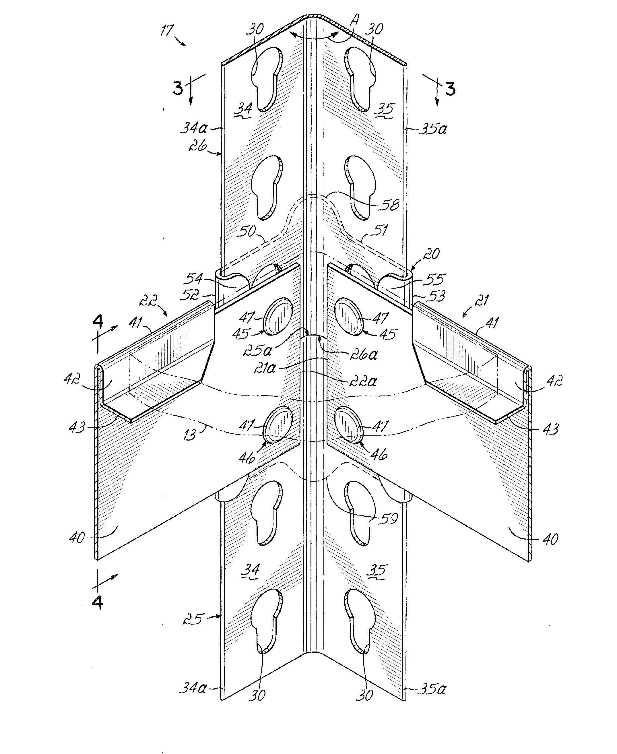
[0046]For purposes of this application, the terms “inner”, “inside” or “interior” refer to post or coupler from within a shelving unit. The terms “outer”, “outside” or “exterior” refer to post or coupler as viewed from without a shelving unit.

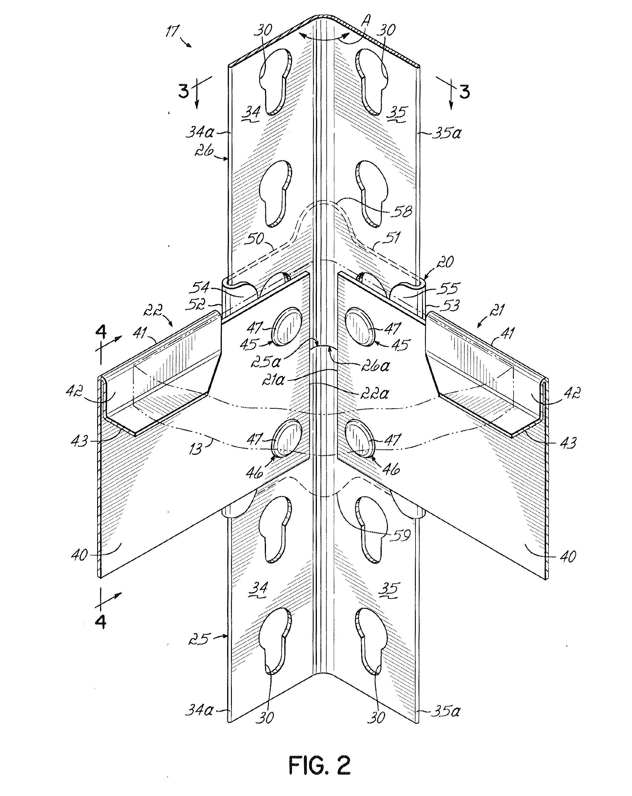
[0047]The coupler 20 best seen in FIG. 2A comprises two major integral coupler flanges 50, 51 disposed at an included angle (at bend 56) to each other at preferably 90°, preferably similar to angle A between the post flanges 34, 35 as will be described.

[0048]Each major flange has a reverse bend or fold 52, 53 and an inwardly directed reverse bend flange 54, 55 respectively turned inwardly, each flange 54, 55 lying parallel to the respective flanges 50, 51 from which they extend.

[0049]A gap G is defined by the respectively adjacent flanges 50, 54 and 51, 55 respectively, this gap being approximately equal to the thickness of post flanges 34, 35 respectively.

[0050]At each end of the bend 56, the coupler 20 includes a longitudinally protruding and...


PUM


Abstract

A post coupler includes coupler flanges, reverse bend flanges extending therealong and rounded end projections extending longitudinally from said coupler flanges defining ends of the coupler, the length of the reverse bend flanges being less than the overall coupler length between ends of the rounded end projections.

Description

PRIORITY CLAIM[0001]This application is a Continuation-in-Part of U.S. patent application Ser. No. 11 / 044,689 filed Jan. 27, 2005, published under Publication No. US2006 / 0163438, entitled “POST COUPLER”, both of which are expressly incorporated herein by reference in their entirety.RELATED PATENT APPLICATIONS[0002]This application is related to co-pending applications filed on even date herewith and including:[0003]U.S. application Ser. No. ______ entitled “DESIGN FOR WRAPPED POST COUPLER”, attorney docket number EDSM-47;[0004]U.S. application Ser. No. ______ entitled “DESIGN FOR POST COUPLER WITH SCALLOPED EDGES”, attorney docket number EDSM-48;[0005]U.S. application Ser. No. ______ entitled “DESIGN FOR POST COUPLER WITH KEYHOLE OPENING”, attorney docket number EDSM-50;[0006]U.S. application Ser. No. ______ entitled “OUTSIDE WRAP POST COUPLER ACCOMMODATING BEAM RIVET”, attorney docket number EDSM-50A;[0007]U.S. application Ser. No. ______ entitled “DESIGN FOR POST COUPLER WITH INSI...

Claims


Application Information

Patent Timeline
IPC IPC(8): A47B96/06
CPCA47B87/0215A47F5/14A47B96/1458
Inventor WOJTOWICZ, DAVID J.ST. GERMAIN, THOMASLISS, MITCHELLDUNAJ, AL
Owner EDSAL MANUFACTURING COMPANY INC
Why Eureka
Try Eureka