
Permanent Magnet Induction Heating and Levitation

Inactive Publication Date: 2011-11-10
MAGNETIC FORCE CORP
View PDF14 Cites 11 Cited by
  • Summary
  • Abstract
  • Description
  • Claims
  • Application Information

AI Technical Summary

Benefits of technology

Prior art permanent magnet heat induction machines suffer from significant complexity, utilizing rotating mechanisms of exceeding complication, the present invention significantly reduces the complexity of the previous arrangements. In one aspect, a permanent magnet thermal generator apparatus has one or more fixed surfaces, with one or more permanent magnets with a North polarity attached to at least one said fixed surface and one or more permanent magnets with a South polarity attached to at least one said fixed surfaces, one or more heating elements comprised of at least one metallic portion whose surface is placed on a significantly parallel plane to at least one of said fixed surfaces and a rotating chamber which is mechanically linked to said heating element so that rotation of the chamber causes motion of the heating element past the permanent magnet's magnetic fields.

Problems solved by technology

However, in many cases, permanent magnet thermal generators are not used.
This results in the burning of additional resources in order to generate the heat for the process.
Most of these produce the heat, but often at the cost of additional complexity.
In most cases, these permanent magnet thermal generators have the undesired effects of putting rotating stresses on the magnets and dispersing the thermal energy among others.

Method used


Image

  • Permanent Magnet Induction Heating and Levitation
  • Permanent Magnet Induction Heating and Levitation
  • Permanent Magnet Induction Heating and Levitation

Examples


Embodiment Construction

To provide an overall understanding of the invention, certain illustrative embodiments will now be described, including apparatus and methods for displaying images. However, it will be understood by one of ordinary skill in the art that the systems and methods described herein may be adapted and modified as is appropriate for the application being addressed and that the systems and methods described herein may be employed in other suitable applications, and that such other additions and modifications will not depart from the scope hereof.

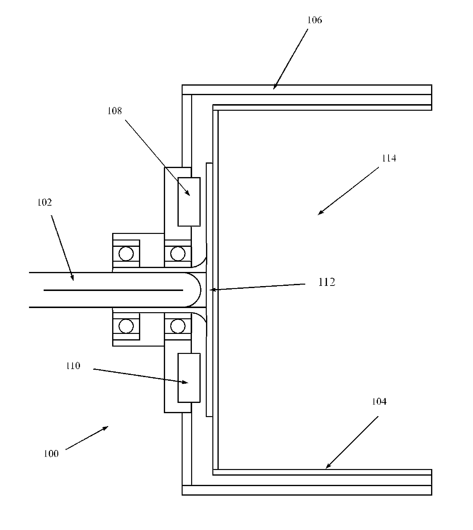
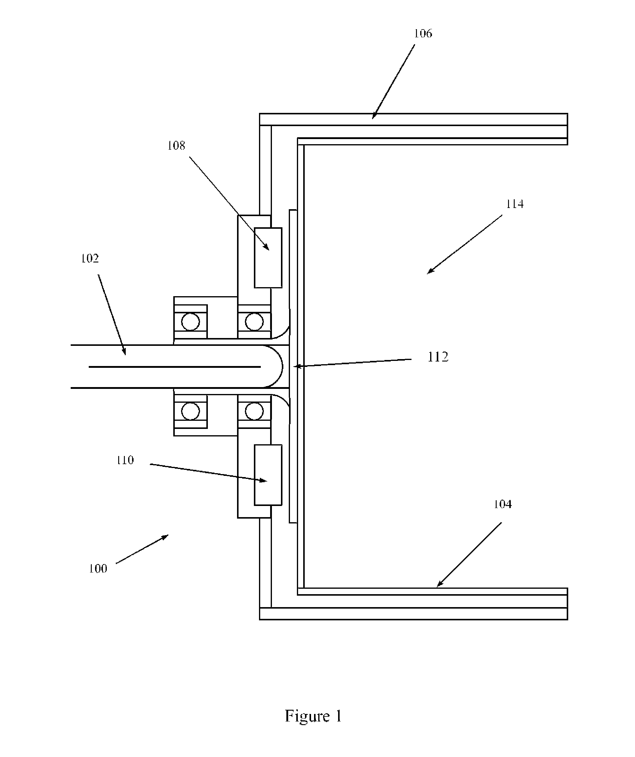
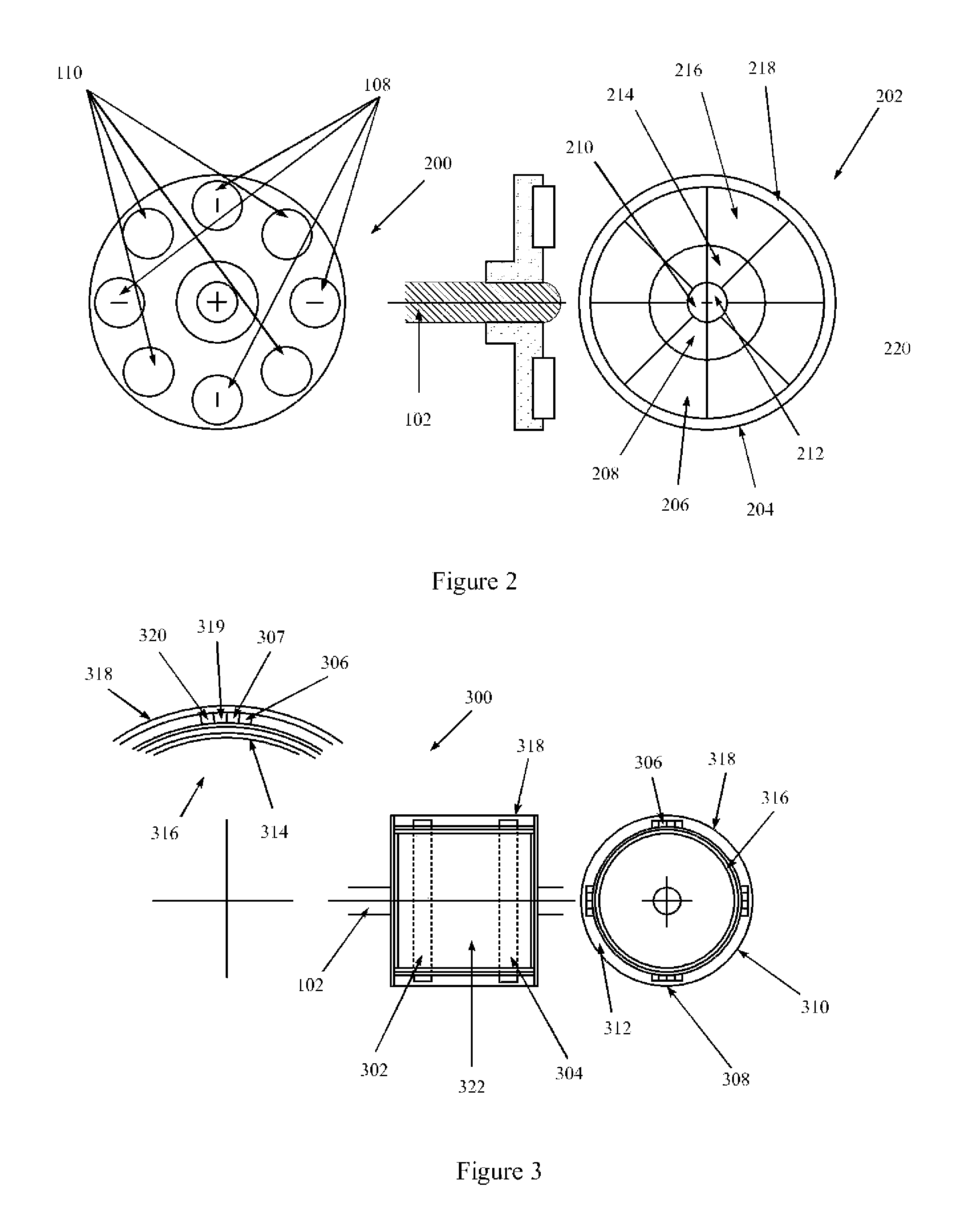
FIG. 1 illustrates one exemplary embodiment of the invention 100, a rotating chamber 114 created by the rotation of the chamber's inner cavity 104 around a fixed (non-rotating) outer chamber 106. In one embodiment, the chamber's rotation is created by the rotation of a central shaft 102. Said shaft may be powered by a number of sources, including human, animal, wind or water via direct, belt or other means. Similarly, the rotation may be created by ...


PUM


Abstract

A permanent magnet thermal generator having a rotating chamber with an attached heat element in close proximity to one or more permanent magnets. The relative motion of the heat element to the magnetic flux from the magnets results in heat generation and in some cases in levitation. Clothe driers, air furnaces, water heaters and other systems incorporating a permanent magnet thermal generator are also set forth.

Description

PATENTS CITEDThe following documents and references are incorporated by reference in their entirety, Skeist et al (U.S. Pat. No. 6,984,897), Gerard et al (U.S. Pat. No. 5,012,060) and Mohr (U.S. Pat. No. 4,671,527).TECHNICAL FIELDThe present invention generally relates to inducing heat and levitation onto surfaces with metallic components from permanent magnets in various configurations.BACKGROUNDMany processes today use fossil fuels (either directly or through the use of electricity generated using said fossil fuels). For example, clothe driers, water heaters, space heaters and other applications such as these are routinely performed using thermic heat generated either via electric radiance, or through the burning of gases such as Propane.The induction of heat via electric current created electromagnetic fields is well understood and has been selected by many designers in order to tightly control the application of the heat (via the intensity of the magnetic field). However, in man...

Claims


Application Information

Patent Timeline
IPC IPC(8): H05B6/10
CPCH05B6/109H05B6/108
Inventor BERDUT TERUEL, ELBERTO
Owner MAGNETIC FORCE CORP
Features
  • Generate Ideas
  • Intellectual Property
  • Life Sciences
  • Materials
  • Tech Scout
  • Unparalleled Data Quality
  • Higher Quality Content
  • 60% Fewer Hallucinations
Learn More