
Roller Mill

a roller mill and drive mechanism technology, applied in the field of roller mills, can solve the problems of reducing the service life of the roller mill and the drive mechanism of the roller mill

Inactive Publication Date: 2011-11-10
F L SMIDTH & CO AS
View PDF3 Cites 1 Cited by
  • Summary
  • Abstract
  • Description
  • Claims
  • Application Information

AI Technical Summary

Benefits of technology

[0004]It is the objective of the present invention to provide a roller mill by means of which the aforementioned disadvantage is eliminated or at least substantially reduced.
[0006]It is hereby obtained that the roller is maintained in tangential direction relative to the grinding table independently of the flexibility of the guide mechanism support, so that the variations in the torsional moment of the mill drive mechanism and hence the loads on the drive mechanism are reduced. This is due to the fact that the vibration-compensation mechanism equalizes the elastic movement affecting the guide mechanism support when the tangential force, which is to be absorbed via the guide mechanism, varies due to a change in the operating environment, thereby actively preventing the roller from moving tangentially relative to the grinding table.

Problems solved by technology

During operation, the drive mechanism of the roller mill is quite often exposed to substantial loads which will reduce its service life, and which are ascribable to major variations in the torsional moment which often appear as high-frequency variations in the torsional moment.

Method used


Image

  • Roller Mill
  • Roller Mill

Examples


Embodiment Construction

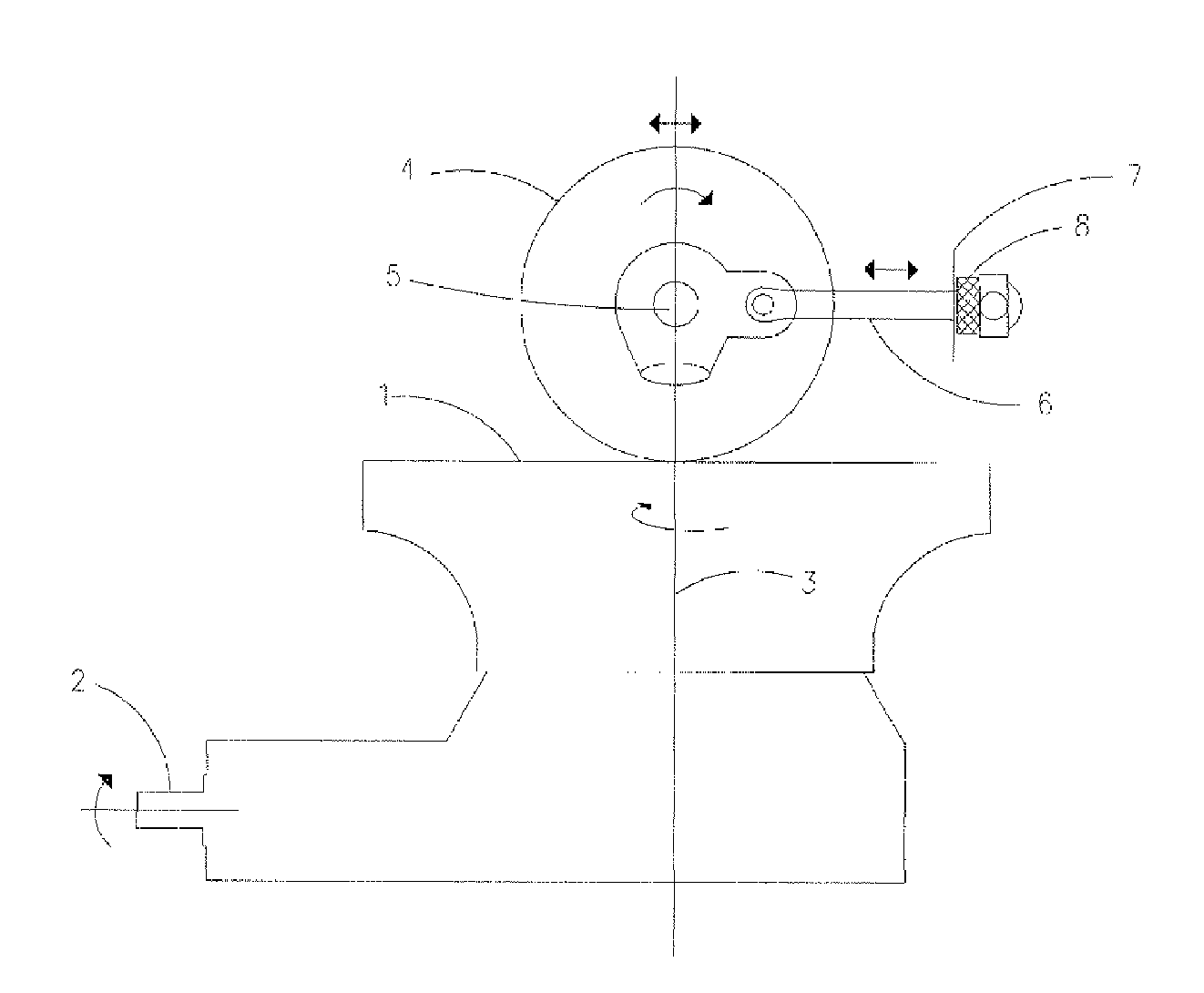
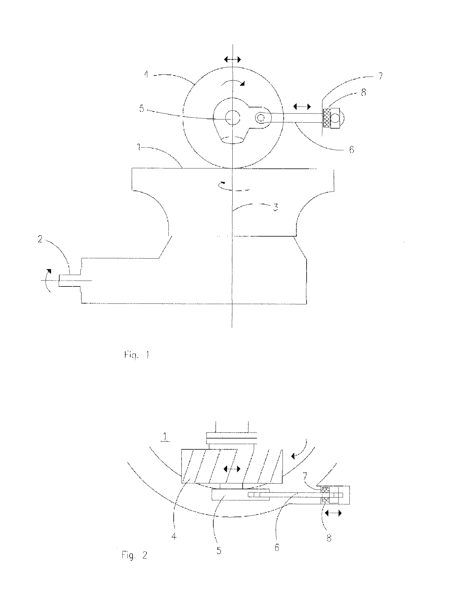
[0015]FIGS. 1 and 2 show a roller mill comprising a grinding table 1, which by means of a drive mechanism 2 is rotatable about a vertical axis 3, a roller 4, which is rotatably mounted on a shaft 5, and being maintained in tangential direction relative to the grinding table by means of a tangential arm 6 which at its respective ends is rotatably connected to the shaft 5 and a support 7, respectively.

[0016]In order to maintain the roller 4 in tangential direction relative to the grinding table 1 independently of the flexibility of the support 7 of the tangential arm, the roller mill comprises a vibration-compensating device 8 which is arranged so in connection with the tangential arm 6 that the vibration-compensating device 8 will equalize the elastic movement affecting the support 7 of the tangential arm 6 when the tangential force, which is to be absorbed via the tangential arm 6, varies due to a change in the operating environment. This will ensure that the roller does not move ta...


PUM


Abstract

A roller mill for grinding particulate material comprises a grinding table which by means of a drive mechanism is rotatable about a vertical axis, at least one roller rotatably mounted on a shaft and being maintained in tangential direction relative to the grinding table by means of a guide mechanism and a support. The roller mill also comprises a vibration-compensating device that is arranged in connection with the guide mechanism to ensure in interaction therewith that the roller is maintained in tangential direction relative to the grinding table.

Description

CROSS REFERENCE TO RELATED APPLICATION[0001]This application is the United States national stage under 35 U.S.C. §371 of International Application No. PCT / IB2010 / 050339, filed on Jan. 26, 2010, which claimed priority to Danish Patent Application No. PA 2009 00138, filed on Jan. 30, 2009. The entirety of these applications is incorporated by reference herein.FIELD OF THE INVENTION[0002]The present invention relates to a roller mill for grinding particulate material such as cement raw materials, cement clinker and similar materials, said roller mill comprising a grinding table which by means of a drive mechanism is rotatable about a vertical axis, at least one roller which is rotatably mounted on a shaft and being maintained in tangential direction relative to the grinding table by means of a guide mechanism and a support.BACKGROUND OF THE INVENTION[0003]Roller mills of the aforementioned kind are generally known. During operation, the drive mechanism of the roller mill is quite often...

Claims


Application Information

Patent Timeline
Patent Type & Authority Applications(United States)
IPC IPC(8): B02C11/00
CPCB02C15/14
Inventor FOLSBERG, JANJESPERSEN, RAINER CLOSTER
Owner F L SMIDTH & CO AS
Learn More