
Image forming apparatus, image forming method and program

Inactive Publication Date: 2011-11-10
CANON KK
View PDF6 Cites 6 Cited by
  • Summary
  • Abstract
  • Description
  • Claims
  • Application Information

AI Technical Summary

Benefits of technology

[0014]According to the present invention, an image forming apparatus, an image forming method, and a program that can perform variable magnification processing while a change in impression and a processing load of the image are suppressed can be provided.

Problems solved by technology

If the data dependent on the resolution is output by specifying variable magnification, there has been a problem that a pixel is missing or only specific lines are overlapped and the like.
However, even if such prior-art technologies are used, the density of the tile image drawn after variable magnification might be different from that of the original tile image before the variable magnification.
Also, a characteristic (a checkered pattern, a vertical line, a diagonal line and the like, for example) of the original tile might be lost by the magnifying / reducing method of the tile image.
However, since an image size for one page is extremely large, it is disadvantageous in terms of a used amount of memory.
If an appropriate variable magnification algorithm considering surrounding pixels is used, a calculation amount is also increased, which may also be disadvantageous in the performance.

Method used


Image

  • Image forming apparatus, image forming method and program
  • Image forming apparatus, image forming method and program
  • Image forming apparatus, image forming method and program

Examples


embodiment 1

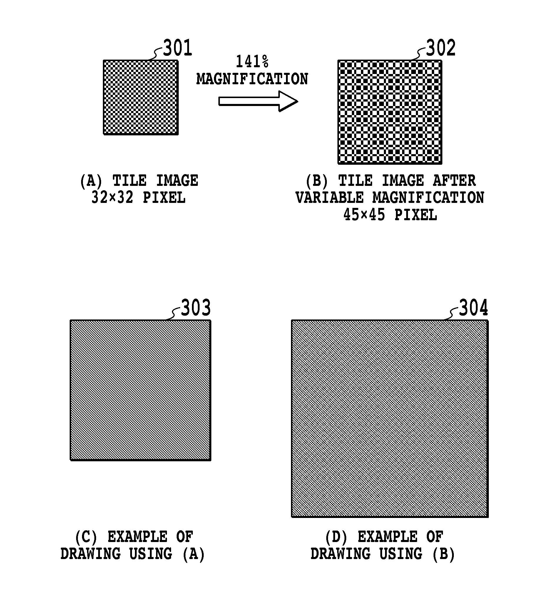
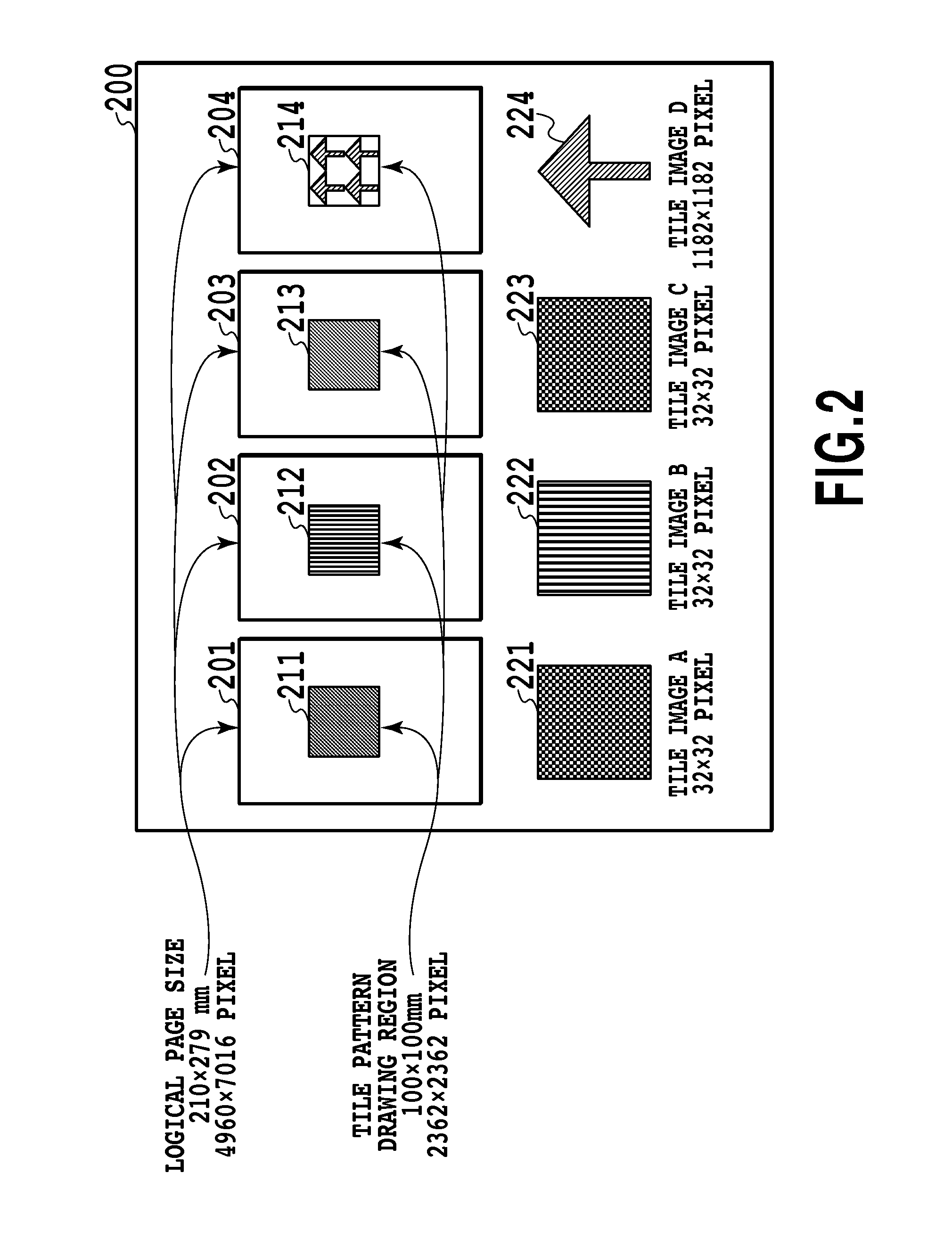
[0035]As Embodiment 1, a case of an enlargement rate at one or more will be described, referring an example where the A4-size test data is to be output to an A3-size (297×420 mm or 7016×9922 pixels in 600 dpi conversion) physical sheet. In order to match the width / height of the output sheet size, the respective logical. page is subjected to variable magnification of enlargement to 141% (=9922 / 7016). Also, the rectangle drawn on the logical page is drawn with the size of 141×141 mm (3331×3331 pixels in 600 dpi conversion).

[0036]First, referring to FIG. 3, a prior-art case in which the tile image itself is variably magnified and drawn will be described. If a tile image 301 having the size of 32 rows and columns with the data resolution (hereinafter, the expression of 32×32 pixels will be used for the size of an image) is drawn with the same magnification, an output image 303 is obtained. If the entire page is magnified to 141% and output, the tile image 301 is magnified with the magni...

embodiment 2

[0055]Subsequently, the case in which the variable magnification rate is less than one will be described using a case of an output into a region having 160×160 pixels in order to perform index print including this test data as an example. In this case, magnification of reduction by an output image width 160 ÷a logical page height 7016=0.023 times ( 1 / 44) is needed. The A4-size logical page is formed into an image having the size of 113×160 pixels. Also, a rectangle drawn on the logical page is drawn with the size of 54×54 pixels.

[0056]Similarly to Embodiment 1, the processing described below is performed by the processor 101 that executes the program stored in the memory 102 and the like.

[0057]In the case of an output using the prior-art technology, the tile image itself is variably magnified and drawn. For example, in the case of reduction of the tile image A having 32×32 pixels by 0.023 times ( 1 / 44), the result is 1×1 pixel. Since the tile image can be expressed only with extreme...


PUM


Abstract

To perform variable magnification processing of an image while a change in an impression of an image and a processing load are suppressed. An image forming apparatus generates a normalized tile image in a tile image and calculates the number of the normalized tile images that can be arranged in a drawing region after variable magnification. If the number is not less than a first threshold value, data including a tile image in which the normalized tile images in the number are arranged in the drawing region after the variable magnification is generated as data after the variable magnification.

Description

BACKGROUND OF THE INVENTION[0001]1. Field of the Invention[0002]The present invention particularly relates to an image forming apparatus, an image forming method and a program that variably magnify and form an image of an electronic document file including a drawing of a tile image.[0003]2. Description of the Related Art[0004]In many of recent printer products, a touch panel including UI as an operation panel is mounted. A media direct print in which a user can connect a storage device such as an SD card or a USB storage to a printer, and directly perform selection of an electronic document file stored in the storage device, print setting and print instruction via an operation panel is widely spreading. With the spread of this type of printers, a method of using electronic document files is being diversified.[0005]In the case of printing from a printer driver having been used so far, appropriate print data according to an output resolution is prepared from an electronic document fil...

Claims


Application Information

Patent Timeline
IPC IPC(8): G06K15/02
CPCG06K15/005G06K15/1848G06K15/1885G06K15/1877G06K15/1868
Inventor SASAKI, HIDEMI
Owner CANON KK
Learn More