Zoom lens system, optical apparatus and method for manufacturing zoom lens system

a technology of optical apparatus and zoom lens, applied in the field of zoom lens system, can solve the problems of flare or ghost images, difficult to obtain high optical performance upon zooming or on the correction of an image blur becoming large, and increase in aberrations, so as to suppress aberration variation, excellent optical performance, and reduce flare and ghost images

Active Publication Date: 2011-11-10
NIKON CORP
View PDF10 Cites 26 Cited by
  • Summary
  • Abstract
  • Description
  • Claims
  • Application Information

AI Technical Summary

Benefits of technology

[0025]The present invention makes it possible to provide a zoom lens system having excellent optical performance with suppressing variation in aberrations upon zooming and reducing flare and ghost images, an optical apparatus equipped with the zoom lens system, and a method for manufacturing the zoom lens system.

Problems solved by technology

However, the conventional zoom lens system has had a problem that when the zoom lens system is made to have a higher zoom ratio, variations in aberrations increase, so that sufficiently high optical performance has been difficult to be obtained upon zooming or upon correcting an image blur becomes large.
At the same time, optical surfaces in such a zoom lens system tend to generate reflection light causing flare or ghost images.

Method used


Image

  • Zoom lens system, optical apparatus and method for manufacturing zoom lens system
  • Zoom lens system, optical apparatus and method for manufacturing zoom lens system
  • Zoom lens system, optical apparatus and method for manufacturing zoom lens system

Examples


first embodiment

[0075]A zoom lens system according to a first embodiment of the present application is explained below.

[0076]A zoom lens system according to the first embodiment includes, in order from an object side along an optical axis, a first lens group having positive refractive power, a second lens group having negative refractive power, a third lens group having positive refractive power, a fourth lens group having negative refractive power, and a fifth lens group having positive refractive power. An aperture stop is disposed to an image side of the second lens group. Upon zooming from a wide-angle end state to a telephoto end state, a distance between the first lens group and the second lens group increases, a distance between the second lens group and the third lens group decreases, a distance between the third lens group and the fourth lens group varies, and a distance between the fourth lens group and the fifth lens group varies, thereby realizing an optical system capable of zooming an...

example 1

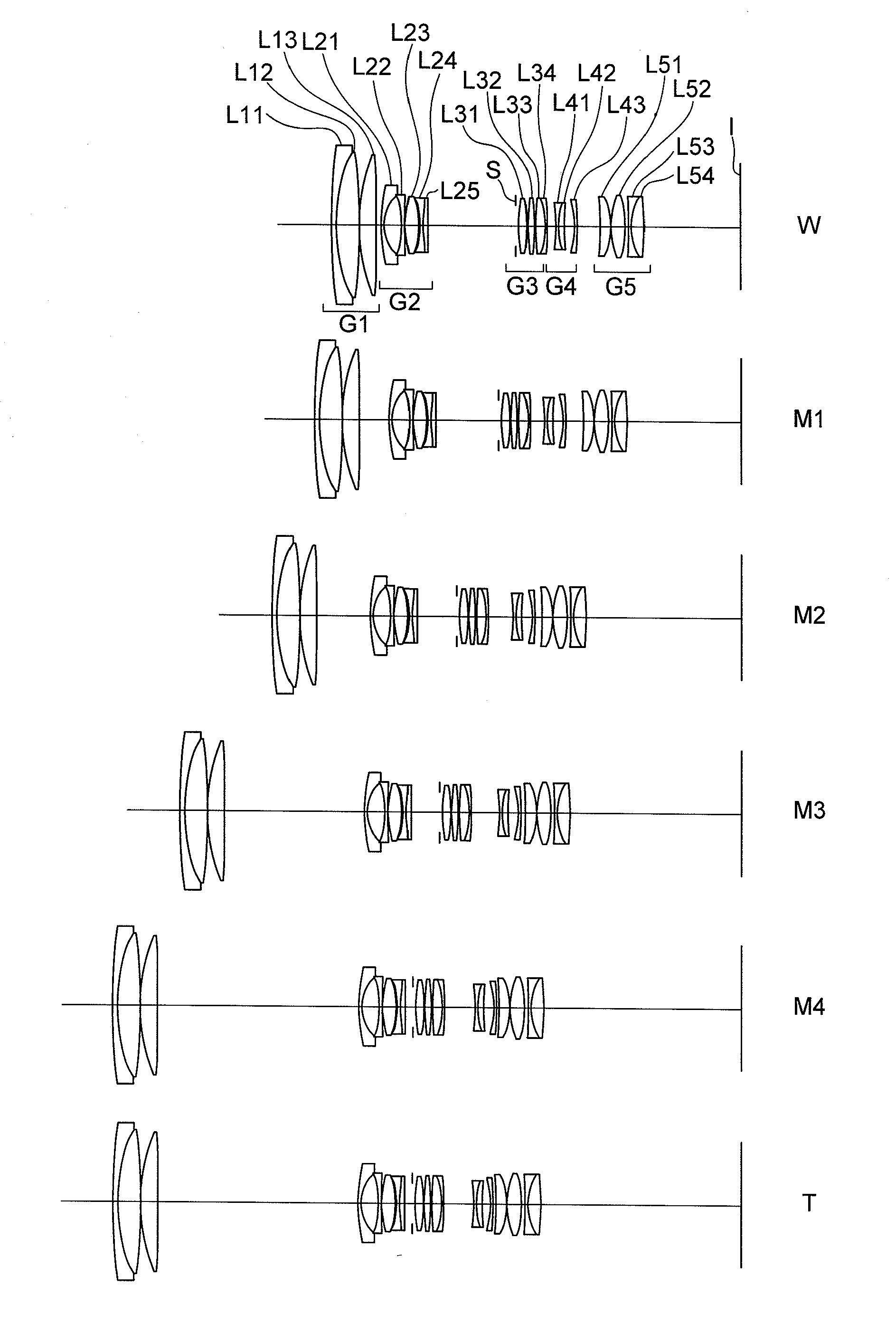
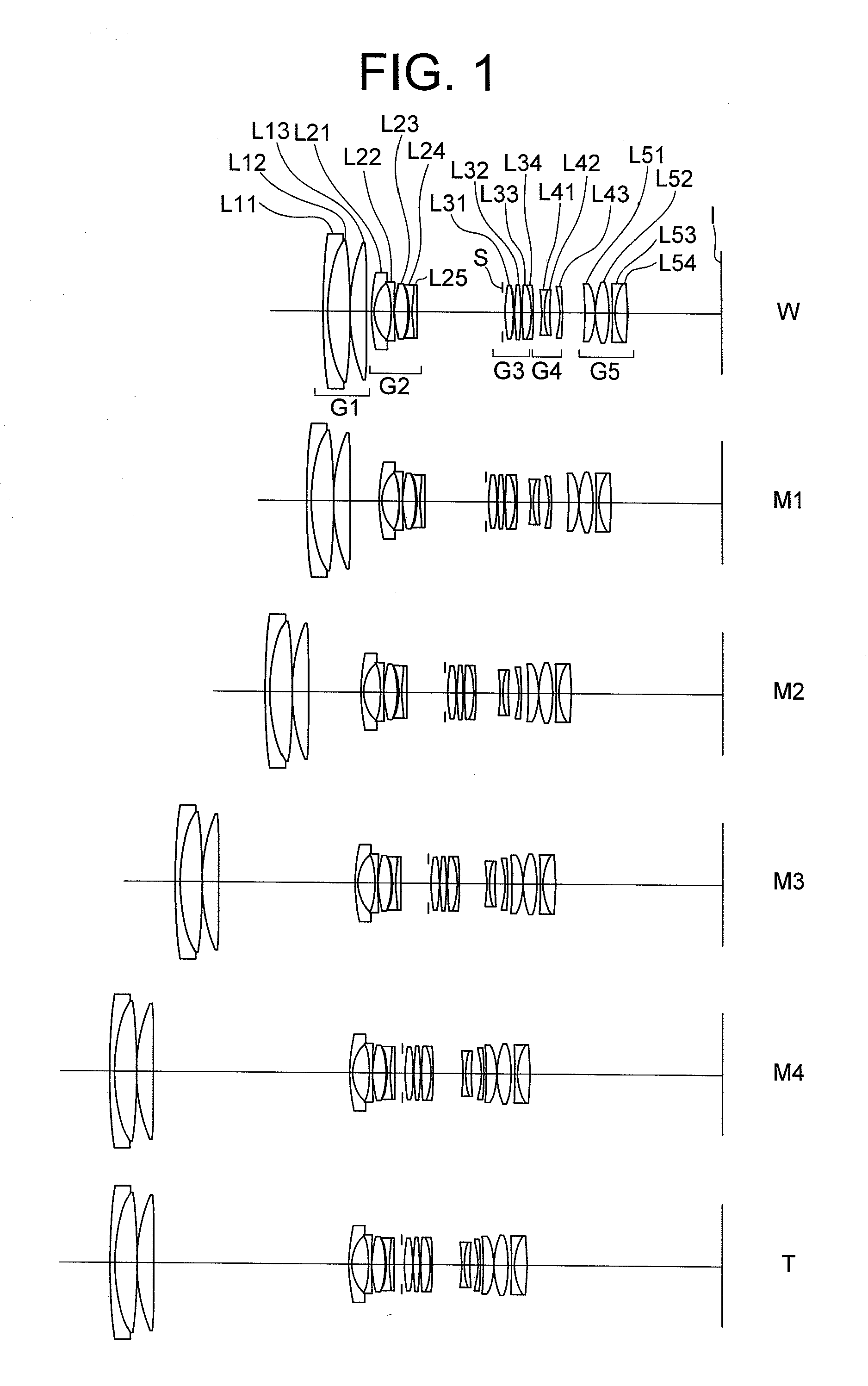
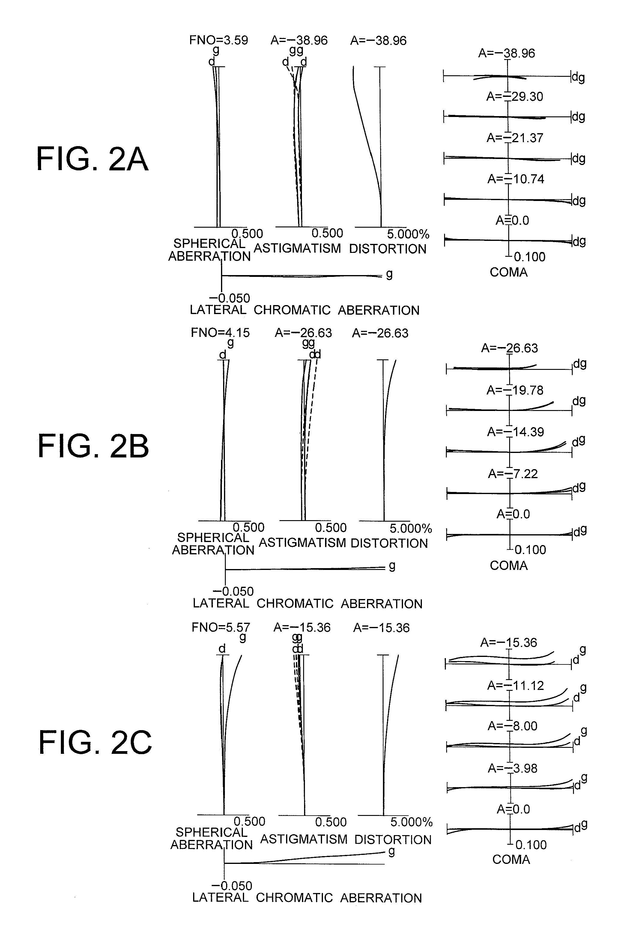
[0170]FIG. 1 is a sectional view showing a configuration of a zoom lens system according to Example 1 of the first embodiment.

[0171]As shown in FIG. 1, the zoom lens system according to Example 1 of the first embodiment is composed of, in order from an object side, a first lens group G1 having positive refractive power, a second lens group G2 having negative refractive power, a third lens group G3 having positive refractive power, a fourth lens group G4 having negative refractive power, and a fifth lens group G5 having positive refractive power.

[0172]Upon zooming from a wide-angle end state W to a telephoto end state T, the first lens group G1 is moved monotonously to the object side, the second lens group G2 is moved to the image side from the wide-angle end state W to a first intermediate focal length state M1, and to the object side from the first intermediate focal length state M1 to the telephoto end state T, and the third lens group G3 is moved monotonously to the object side ...

example 2

[0195]FIG. 4 is a sectional view showing a configuration of a zoom lens system according to Example 2 of the first embodiment.

[0196]As shown in FIG. 4, the zoom lens system according to Example 2 of the first embodiment is composed of, in order from an object side, a first lens group G1 having positive refractive power, a second lens group G2 having negative refractive power, a third lens group G3 having positive refractive power, a fourth lens group G4 having negative refractive power, and a fifth lens group G5 having positive refractive power.

[0197]Upon zooming from a wide-angle end state W to a telephoto end state T, the first lens group G1 is moved monotonously to the object side, the second lens group G2 is moved to the image side from the wide-angle end state W to a first intermediate focal length state M1, and to the object side from the first intermediate focal length state M1 to the telephoto end state T, and the third lens group G3 is moved monotonously to the object side ...


PUM

PropertyMeasurementUnit
refractive indexaaaaaaaaaa
refractive poweraaaaaaaaaa
distanceaaaaaaaaaa

Abstract

Including, in order from an object side: a first lens group G1 having positive power; a second lens group G2 having negative power; a third lens group G3 having positive power; a fourth lens group G4 having negative power; and a fifth group G5 having positive power, an aperture stop being disposed to an image side of the second lens group, upon zooming from a wide-angle end state to a telephoto end state, a distance between the first lens group G1 and the second lens group G2 increasing, a distance between the second lens group G2 and the third lens group G3 decreasing, a distance between the third lens group G3 and the fourth lens group G4 varying, and a distance between the fourth lens group G4 and the fifth lens group G5 varying, and given conditionals being satisfied, thereby providing a zoom lens system having high optical performance with suppressing variation in aberrations, an optical apparatus equipped therewith, and a method for manufacturing the zoom lens system.

Description

[0001]The disclosure of the following priority applications are herein incorporated by reference:[0002]Japanese Patent Application No. 2010-050798 filed on Mar. 8, 2010;[0003]Japanese Patent Application No. 2010-050804 filed on Mar. 8, 2010;[0004]Japanese Patent Application No. 2010-050835 filed on Mar. 8, 2010;[0005]Japanese Patent Application No. 2010-050846 filed on Mar. 8, 2010;[0006]Japanese Patent Application No. 2011-020123 filed on Feb. 1, 2011; and[0007]Japanese Patent Application No. 2011-020133 filed on Feb. 1, 2011.BACKGROUND OF THE INVENTION[0008]1. Field of the Invention[0009]The present invention relates to a zoom lens system, an optical apparatus equipped with the zoom lens system and a method for manufacturing the zoom lens system.[0010]2. Related Background Art[0011]There have been proposed zoom lens systems having a positive lens group disposed to the most object side used as an interchangeable lens for a single lens reflex camera and the like disclosed in such as...

Claims


Application Information

Patent Timeline
Patent Type & Authority Applications(United States)
IPC IPC(8): G02B15/14B05D5/06G02B1/11
CPCG02B15/173Y10T29/49826G02B15/14G02B15/16G02B15/143105G02B15/144105G02B15/144113G02B15/145121
Inventor OBAMA, AKIHIKOYOKOI, NORIKAZUTANAKA, ISSEI
Owner NIKON CORP
Why Eureka
Try Eureka