
Develop roller, develop unit, process cartridge, and image forming apparatus

a technology of development sleeves and development sleeves, applied in electrographic process sleeves, optics, instruments, etc., can solve the problems of increasing manufacture costs, and weakening the color of generated images, so as to prevent the effect of reducing the amount of developer to deliver

Inactive Publication Date: 2011-11-10
RICOH KK
View PDF19 Cites 5 Cited by
  • Summary
  • Abstract
  • Description
  • Claims
  • Application Information

AI Technical Summary

Benefits of technology

[0020]The present invention aims to provide a develop roller and a develop unit which can prevent a reduction in amount of developer to deliver due to a degradation over time and unevenness in density of images generated as well as to provide a process cartridge and an image forming apparatus incorporating such a develop unit.

Problems solved by technology

However, there is a problem with the sandblasted develop sleeve in terms of durability since the unevenness on the surface is extremely fine so that it is abraded and the surface is gone smooth as the number of prints increases with time.
Accordingly, amount of developer the develop sleeve delivers decreases gradually, weakening the color of generated images.
However, this is not desirable because of an increase in manufacture costs.
However, it has a problem with this develop sleeve that image density may periodically vary or uneven pitch may occur because of a difference in delivery amount of developer between the grooves and non-groove portions.
Generally, the deeper the grooves, the better the developer delivery performance but the more likely uneven pitch occurs due to a difference in develop field intensity of the grooves and the non-groove portions.
With shallower grooves, toner, additives, or carrier in the developer is likely to get stuck in the grooves, largely decreasing the developer delivery performance and amount of developer attracted.
Insufficient delivery attraction is likely to cause uneven pitch.
However, along with improvement in image reproducibility by advanced image forming technique such as adaption of toner or carrier of smaller particle size or proximity developing, the uneven pitch is more noticeable.
However, there is a problem with this develop sleeve that since the grooves are formed by drawing an aluminum tube with a dice by cold working and finished by cutting or grinding and need be disposed with a narrower interval, there may be an increase in deviation of the depth of the grooves.
The deviation in the groove depth may cause unevenness in image density.
However, it increases the number of processing steps and manufacture costs.
However, the surface of the develop sleeve is randomly hit with a linear material by sandblasting so that it is difficult to set a proper processing condition in order to maintain an optimum attraction amount of the developer and elongate the longetivity of the develop sleeve.
It is also difficult to increase the attraction amount of developer in view of high-quality image generation with a higher-speed machine in the future.
This may cause the doctor gap in the longitudinal center of the develop roller to be widened beyond both ends of the develop roller.
Accordingly, a problem arises that toner supply amount in the longitudinal center of the develop roller is larger than that in both of the end portions, causing unevenness in image density in the longitudinal direction of the develop roller.

Method used


Image

  • Develop roller, develop unit, process cartridge, and image forming apparatus
  • Develop roller, develop unit, process cartridge, and image forming apparatus
  • Develop roller, develop unit, process cartridge, and image forming apparatus

Examples


Embodiment Construction

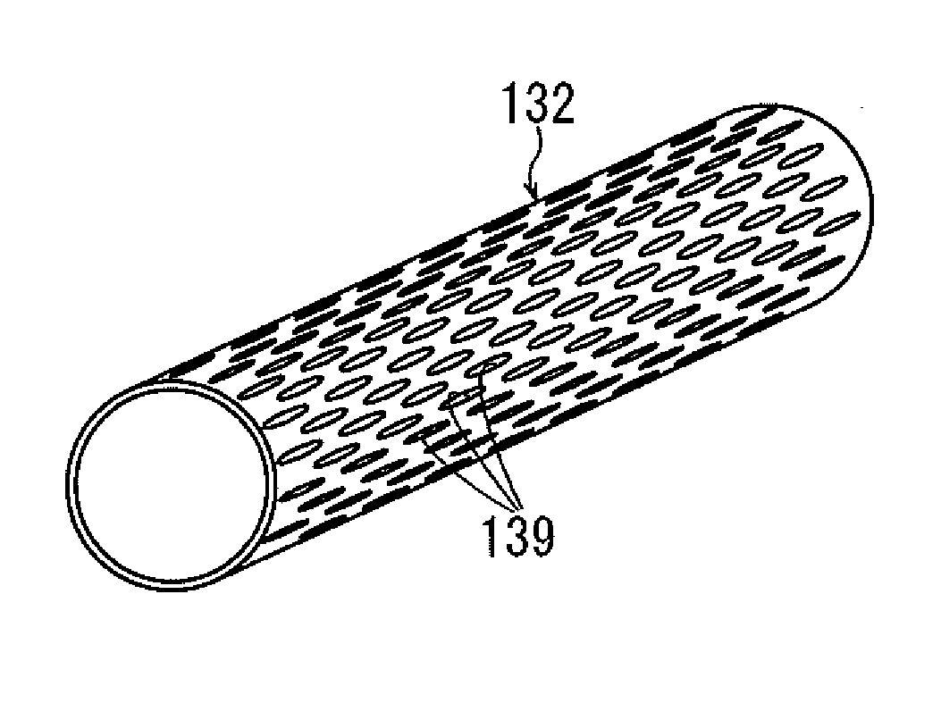
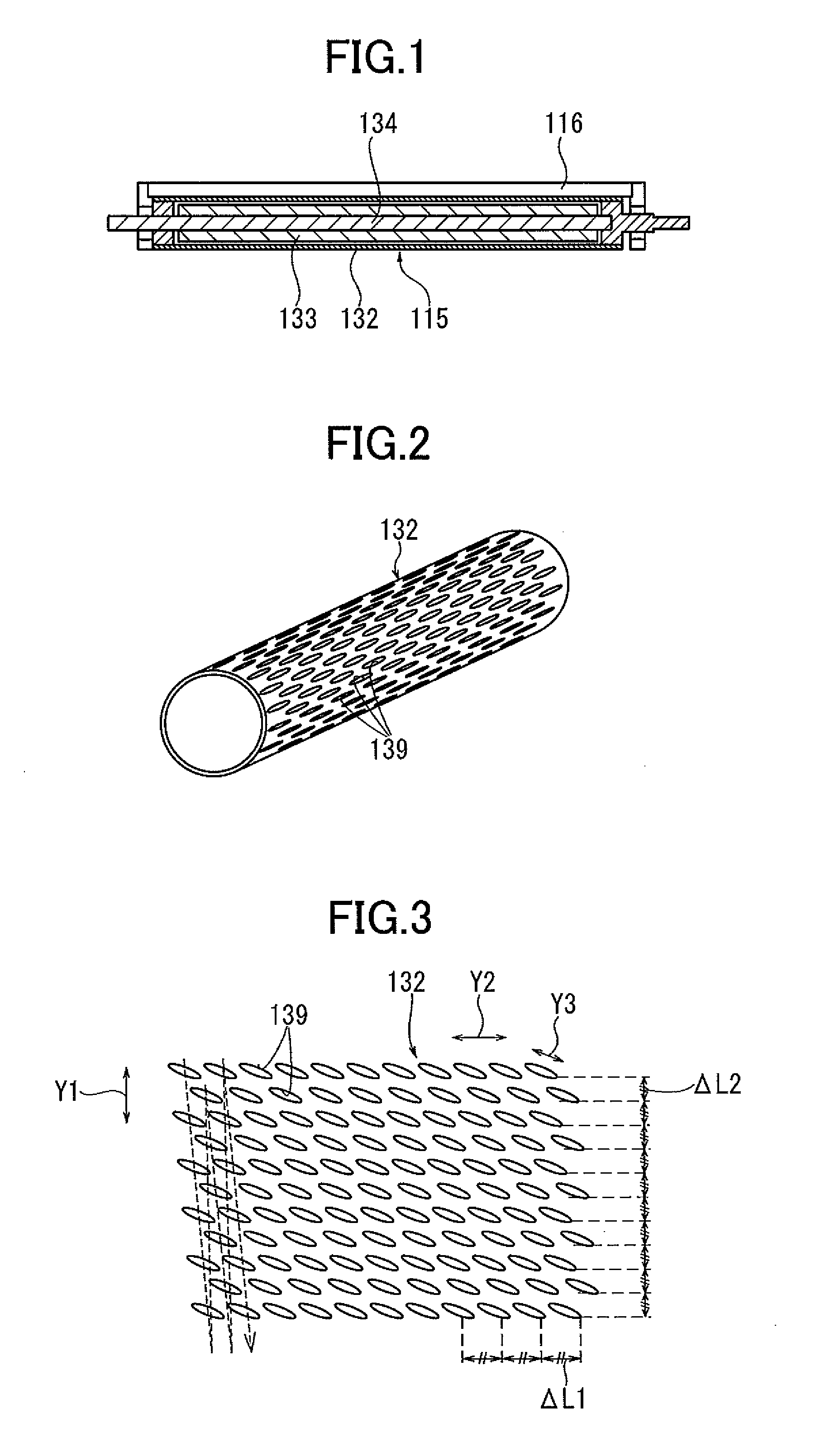
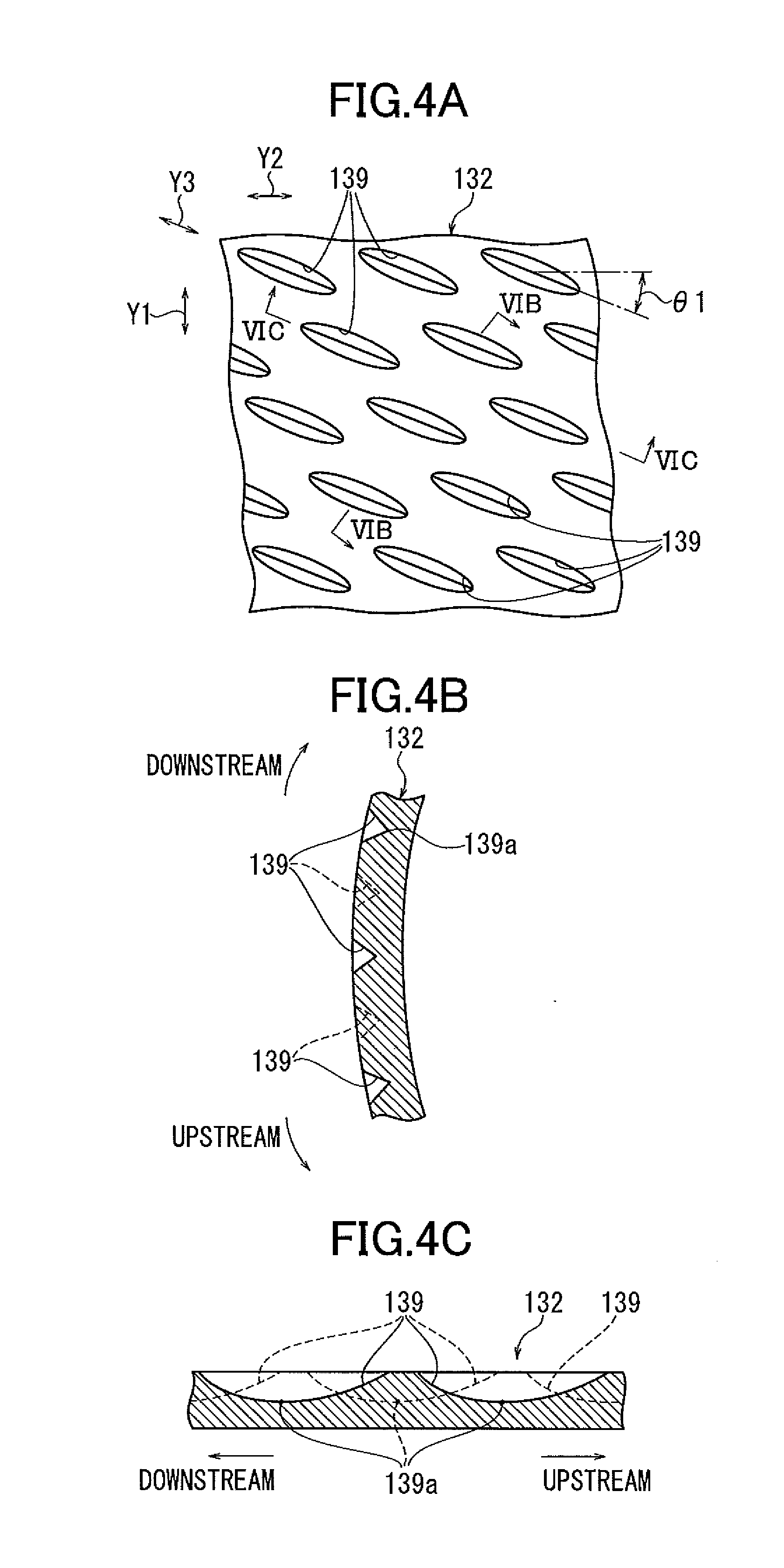
[0050]Hereinafter, one embodiment of the present invention will be described in detail with reference to FIG. 1 to FIG. 9. FIG. 1 cross-sectionally shows a develop roller according to one embodiment of the present invention. FIG. 2 is a perspective view of a develop sleeve in FIG. 1. FIG. 3 is a developed view of the surface of the develop sleeve in FIG. 2. FIG. 4A is an enlarged view of a part of the develop sleeve surface in FIG. 2, FIG. 4B is a cross section of the same along a VIB to VIB line in FIG. 4A and FIG. 4C is a cross section of the same along a VIC to VIC line in FIG. 4A.

[0051]In FIG. 1 the develop roller 115 comprises a metal core 134, a cylindrical develop sleeve 132 and a magnet roller 133. The metal core 134 is parallel to a photoreceptor drum 108 in a longitudinal direction, fixed in a housing 125 of a later-described image forming apparatus 101 and does not rotate.

[0052]The magnet roller 133 is cylindrical made of a magnetic material and comprises a not-shown plur...


PUM


Abstract

A develop roller includes a magnet roller, and a develop sleeve containing the magnet roller and comprising a plurality of depressions in an elliptic shape regularly arranged with an interval in a longitudinal direction on a surface onto which developer is attracted by a magnetic force of the magnet roller, wherein the depressions are arranged such that a longitudinal direction of the depressions is intersected with the longitudinal direction of the develop sleeve, and a downstream side of the depressions are formed to be deeper than an upstream side in a rotary direction of the develop sleeve.

Description

CROSS REFERENCE TO RELATED APPLICATION [0001]The present application is based on and claims priority from Japanese Patent Application No. 2010-106150, filed on May 6, 2010, the disclosure of which is hereby incorporated by reference in its entirety.BACKGROUND OF THE INVENTION [0002]1. Field of the Invention[0003]The present invention relates to a develop roller and a develop unit used in a copier, a facsimile machine, or a printer to deliver developer on a develop sleeve to a develop area between a photoreceptor drum and a develop sleeve, develop an electrostatic latent image on the photoreceptor drum, and generate a toner image as well as to a process cartridge and an image forming apparatus including such a develop unit.[0004]2. Description of the Prior Art[0005]Japanese Patent Application Publication No. 2003-255692 (Reference 1), No. 2004-191835 (Reference 2), and No. 2007-86091 (Reference 3) disclose a develop sleeve whose surface is sandblasted, grooved or processed by electro...

Claims


Application Information

Patent Timeline
Patent Type & Authority Applications(United States)
IPC IPC(8): G03G15/09
CPCG03G2215/0634G03G15/0818
Inventor OHSAWA, MASAYUKIKOJIMA, TOSHIOKOETSUKA, KYOHTATAKANO, YOSHIYUKIKAMIYA, NORIYUKIINNAMI, TAKASHITERASAKA, TAKUMI
Owner RICOH KK
Learn More