

Beam blade windshield wiper assembly
- Summary
- Abstract
- Description
- Claims
- Application Information
AI Technical Summary
Benefits of technology
Problems solved by technology
Method used
Image

Examples
Embodiment Construction
)
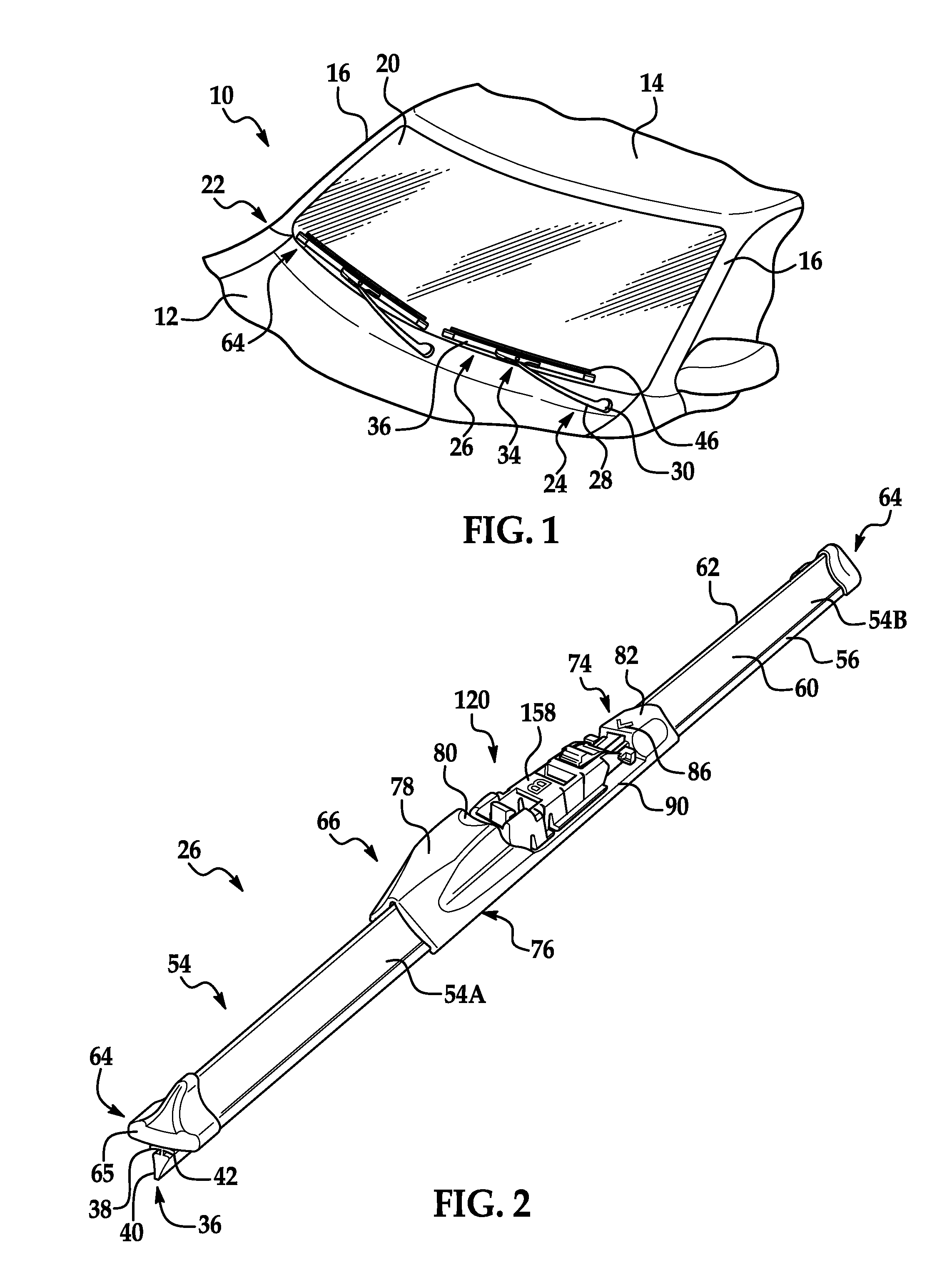
[0032]Referring now to the figures, where like numerals are used to designate like structure, a portion of a vehicle is schematically illustrated at 10 in FIG. 1. The vehicle includes a cowl 12, a roof 14, and a pair of laterally spaced front or “A” pillars 16 extending between the roof 14 and the cowl 12. The A-pillars 16, roof 14, and cowl 12 cooperate to support a curved or “swept back” glass windshield 20 located therebetween.
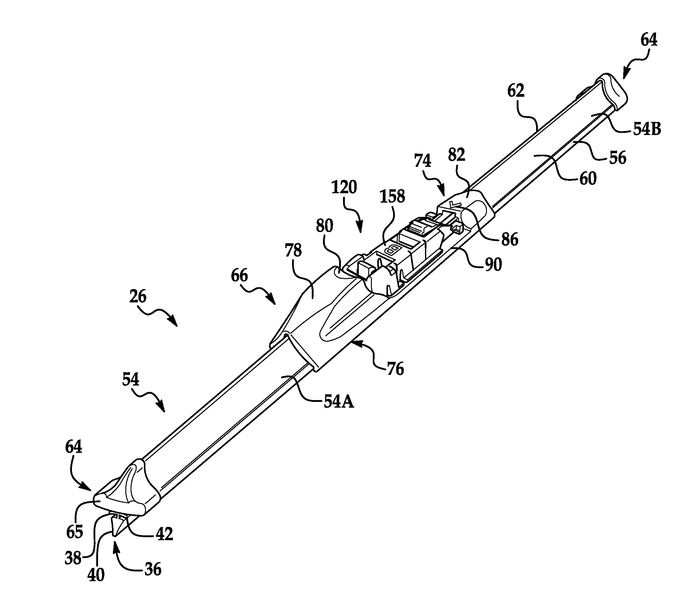
[0033]A wiper system is generally indicated at 22 in FIG. 1 and is employed to clean the glass windshield 20. The wiper system 22 includes a wiper arm, generally indicated at 24 and a beam blade windshield wiper assembly of the present invention, generally indicated at 26, (hereinafter referred to as a “wiper assembly”). The wiper assembly 26 is releasably engaged to the wiper arm 24 and adapted to clean the surface to be wiped, namely a windshield 20. Those having ordinary skill in the art will appreciate that a wiper system 22 may include more than wiper...
PUM
 Abstract
Description
Claims
Application Information