Finisher for cutting or scoring receiver

a receiver and finishing technology, applied in the field of finishing printed sheets, can solve the problems of not being able to produce more than 10 cut patterns without manual intervention, requiring more frequent changes to the finishing sequence, and not being able to meet the needs of consumer occupied environments

Inactive Publication Date: 2011-11-17
MIDWEST ATHLETICS & SPORTS ALLIANCE LLC
View PDF4 Cites 7 Cited by
  • Summary
  • Abstract
  • Description
  • Claims
  • Application Information

AI Technical Summary

Benefits of technology

[0013]An advantage of this invention is that it provides programmable, per-receiver or per-sheet control of cutting and scoring. It provides adjustable depth of cut and depth of score. In various embodiments, it cuts or scores without buckling the receiver. It is small and lightweight.

Problems solved by technology

Conventional finishing equipment is typically not suited for use in consumer occupied environments such as stores or business establishments, and typically requires trained personnel to safely and effectively use it.
Furthermore, unlike offset presses which run a large number of copies of a single print job, digital printers can produce small numbers of copies of a job, requiring more frequent changes to the finishing sequence.
The PL265 cutter can only store 10 cutting programs, so cannot produce more than 10 cut patterns without manual intervention.
However, this device cannot score programmably or across only part of a receiver, and cannot cut sheets.
However, this scheme can waste paper due to trimming.
Furthermore, this scheme is not well-suited to high-speed operation in which receivers should be moved at a constant velocity through the entire printing and finishing apparatus.
However, the machine requires manual loading and unloading.
Furthermore, the CRICUT moves the sheet to be cut back and forth during cutting, making it unsuitable for high-volume applications that need continuous-speed sheet transport.
However, these shears are strictly manual, and are not suitable for automated use.

Method used


Image

  • Finisher for cutting or scoring receiver
  • Finisher for cutting or scoring receiver
  • Finisher for cutting or scoring receiver

Examples


Embodiment Construction

[0024]As used herein, the terms “parallel” and “perpendicular” have a tolerance of ±5°.

[0025]As used herein, “sheet” is a discrete piece of media, such as receiver media for an electrophotographic printer (described below). Sheets have a length and a width. “Face” refers to one side of the sheet, whether before or after folding.

[0026]A computer program product can include one or more storage media, for example; magnetic storage media such as magnetic disk (such as a floppy disk) or magnetic tape; optical storage media such as optical disk, optical tape, or machine readable bar code; solid-state electronic storage devices such as random access memory (RAM), or read-only memory (ROM); or any other physical device or media employed to store a computer program having instructions for controlling one or more computers to practice methods useful with the present invention.

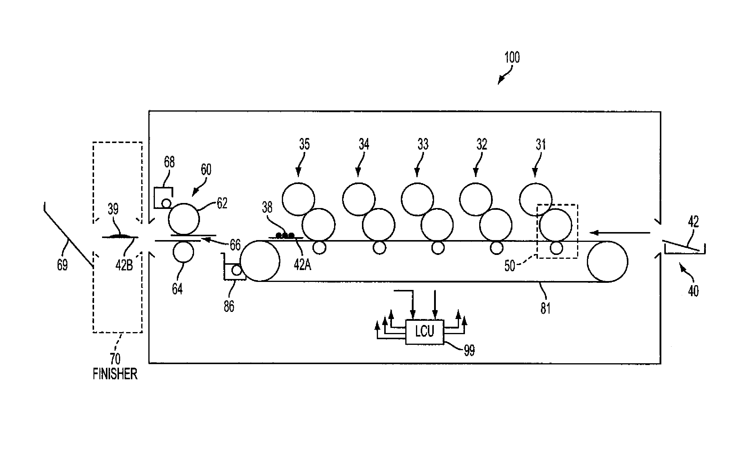
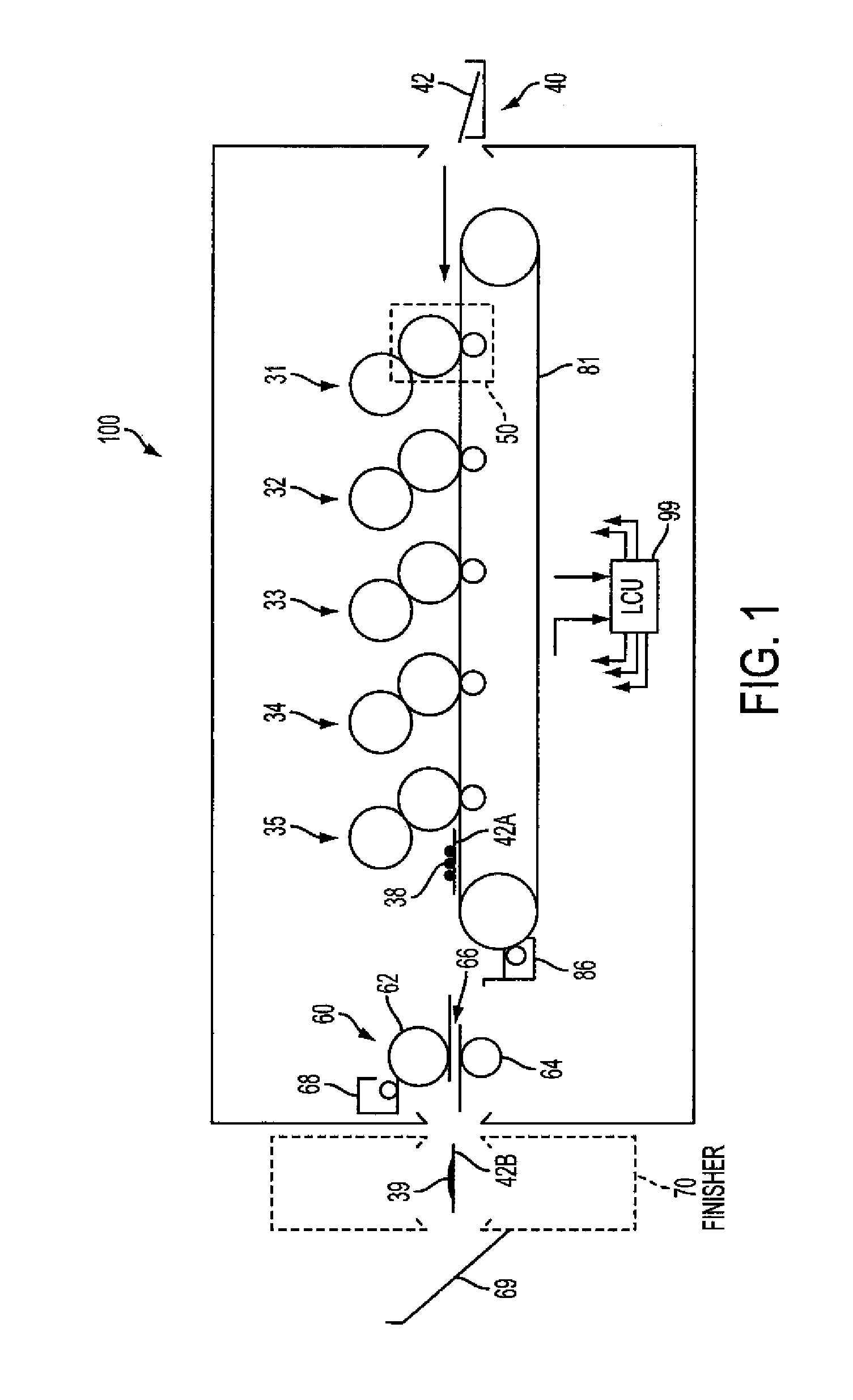
[0027]Electrophotography is a useful process for printing images on a receiver (or “imaging substrate”), such as a pie...


PUM

PropertyMeasurementUnit
timeaaaaaaaaaa
speedaaaaaaaaaa
distanceaaaaaaaaaa

Abstract

A finisher for a receiver moving in a feed direction includes a cutting device having a cutting blade and a scoring blade on opposite sides of the receiver and oriented perpendicular to the feed direction, and a scoring notch on the opposite side of the receiver from, and parallel to, the scoring blade. An actuator selectively causes the scoring blade to engage the scoring notch as the receiver moves between the scoring blade and scoring notch, so that the receiver is scored, or causes the cutting blade to engage the scoring blade, so that the receiver is cut. A controller receives a job specification including one or more cut or score location(s) on the receiver and causes the receiver to be cut at the cut location(s) or scored at the score location(s).

Description

FIELD OF THE INVENTION[0001]This invention pertains to the field of finishing printed sheets, and more particularly to such printed sheets produced using electrophotography.BACKGROUND OF THE INVENTION[0002]Customers of print jobs can require finishing steps for their jobs. These steps include, for example, folding printed or blank sheets, cutting sheets, scoring sheets, trimming sheets to size and shape, cutting specialty shapes into the edges or interior of a sheet, forming multiple sheets into bound signatures or booklets, binding individual pages or signatures into books, and fastening covers to books by e.g. stapling, saddle-stitching, or gluing. These operations are to be performed on receiver materials of various types, including various thicknesses of paper, for example ranging from India paper to card stock. For example, a number of business cards are printed together on a large sheet of stiff card stock. After printing, individual cards are produced by cutting the sheets of...

Claims


Application Information

Patent Timeline
Patent Type & Authority Applications(United States)
IPC IPC(8): B26D9/00
CPCB26D1/08B26D1/085B26D3/08B26D11/00B26D5/08B26D5/083B26D7/27B26D3/085Y10T83/0207Y10T83/023Y10T83/0333Y10T83/141Y10T83/8742
Inventor RIMAI, DONALD S.SHIFLEY, JAMES D.KWARTA, BRIAN J.
Owner MIDWEST ATHLETICS & SPORTS ALLIANCE LLC
Why Eureka
Try Eureka