Pneumatic tire

a technology of pneumatic tires and grooves, which is applied in the direction of non-skid devices, vehicle components, transportation and packaging, etc., can solve the problems of reducing the width of grooves, cracks (groove cracks), and the durability of tires, so as to reduce the convergence of strain, prevent the generation of groove cracks, and restrict the deformation of groove portions

Inactive Publication Date: 2011-11-17
TOYO TIRE & RUBBER CO LTD
View PDF4 Cites 6 Cited by
  • Summary
  • Abstract
  • Description
  • Claims
  • Application Information

AI Technical Summary

Benefits of technology

[0014]In the pneumatic tire, when a large load is applied to the groove portion during running, each of the protruding portions supports the land portions partitioned by the groove portions, thereby deformation of the groove portion can be restricted. As a result, convergence of strain at the bottom of groove is restricted, and thus groove cracks can be prevented from being generated. Further, since the cut-off portions that are opened to the wall surface of the groove are formed alternately with the protruding portions, the cut-off portions absorb the stress at the base portion of the protruding portions supporting the land portions, and thus the convergence of strain can be reduced. As a result, chipping-off or break-off of the protruding portions can be prevented as well as contact pressure can be restricted from increasing at the edge portion adjacent to the protruding portion. Thus irregular wear of the tire can be prevented.
[0015]In the pneumatic tire, each of the protruding portions is preferably formed being separated away from the bottom of the groove portion to the outer side thereof as viewed in a radial direction of the tire. With this constitution, since a larger curvature radius can be set at the bottom of the groove, deformation of the groove portions can be restricted; and thus groove cracks can be prevented from being generated more reliably.
[0016]In the pneumatic tire, the distance between the protruding portion and the cut-off portion is preferably smaller than the width of the protruding portion as viewed in the extending direction of the groove portion. With this constitution, the protruding portions and the cut-off portions are disposed at appropriate distance from each other. Therefore, the stress at the base portion of the protruding portions can be absorbed effectively by the cut-off portions. As a result, irregular wear of the tire as well as chipping-off and break-off of the protruding portions can be prevented more reliably.
[0017]In the pneumatic tire, the height of each of the protruding portions from the groove wall surface is preferably 20 to 60% of the width of the groove portion. With this constitution, the stress at the base portion of the protruding portions can be reduced while ensuring the drainage performance of the groove portions and the protruding portions reliably support the land portions. Thus, deformation of the groove portions can be restricted.
[0018]In the pneumatic tire, the protruding portions and the cut-off portions are formed on both wall surfaces of the groove portion, wherein the protruding portions on both wall surfaces of the groove portion may be disposed so as to opposite to each other as viewed in a groove width direction. With this constitution, since the protruding portions support each other, particularly in the groove portions having a relatively large width, deformation of the groove portions can be effectively restricted.
[0019]In the pneumatic tire, the protruding portions and the cut-off portions are formed on both wall surfaces of the groove portion, wherein the protruding portions on both wall surfaces of the groove portion may be disposed so as not to opposite to each other as viewed in a groove width direction. With this constitution, the protruding portions come into contact with the opposing wall surface of the groove and support the land portion respectively. Particularly in the groove portion having a relatively small width, deformation thereof can be effectively restricted.

Problems solved by technology

When brake is applied or while turning a vehicle, these groove portions are subjected to a large load causing a large deformation in a direction reducing the groove width.
At this time, strain converges on the bottom of groove causing cracks (groove cracks).
Thus, the deformation of tire may cause a problem in an aspect of the durability of the tire.
However, this technique cannot restrict deformation of groove portion, particularly on the tread surface side portion of tire.
Therefore, tires are prone to irregular wear in edge line area (edge portion) formed by groove portion and tread surface therebetween.
However, this technique cannot prevent the generation of cracks at the bottom of groove.
However, when protruding portions support each other, strain converges on base portion of the protruding portions causing cracks in this area.
As a result, this area tends to be partially worn and thus a irregular wear is generated.
Also in this technique, the above problems such as chipping-off and break-off of the protruding portion as well as irregular wear of the tire still remains.
However, in this pneumatic tire, when the protruding portions come into contact with each other or when the protruding portions and opposing wall surfaces of the groove come into contact with each other to support each other, there remain the above problems such as chipping-off and break-off of the protruding portion as well as irregular wear of the tire.Patent document 1; Japanese Unexamined Patent Publication No. 06-191231Patent document 2; Japanese Unexamined Patent Publication No. 2006-137231Patent document 3; Japanese Unexamined Patent Publication No. 2005-263087

Method used


Image

  • Pneumatic tire
  • Pneumatic tire
  • Pneumatic tire

Examples


example 1

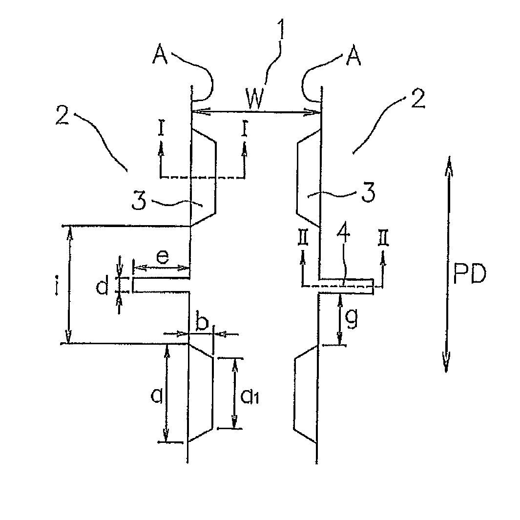
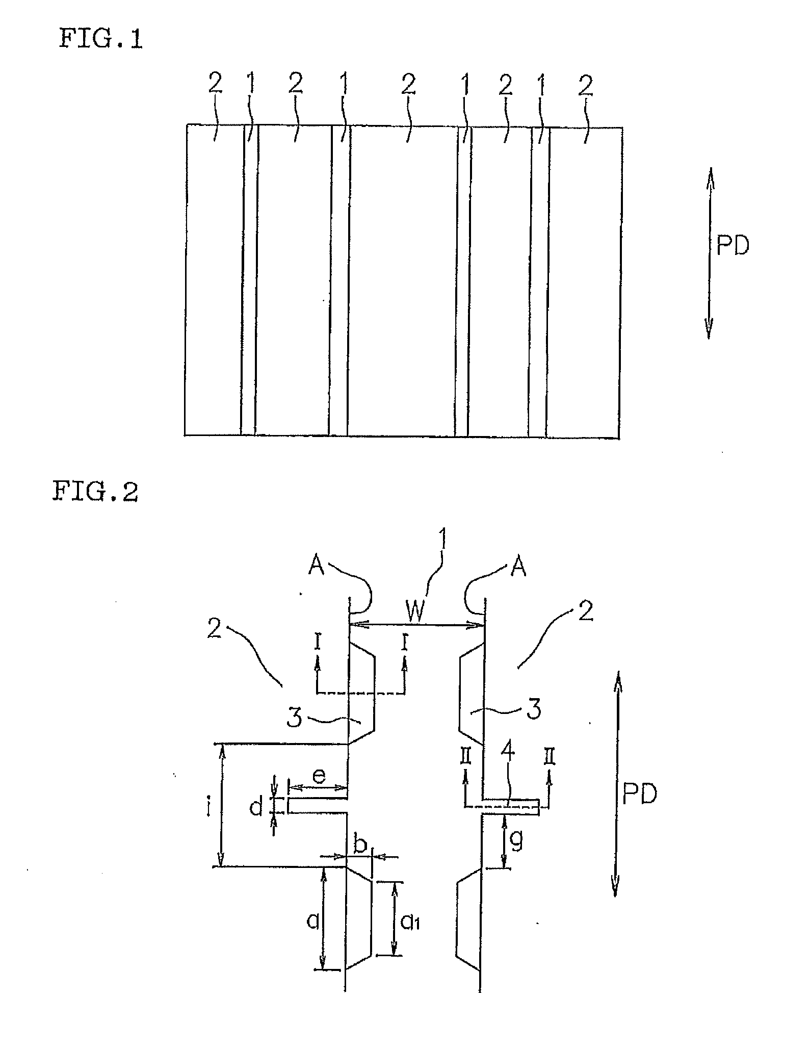
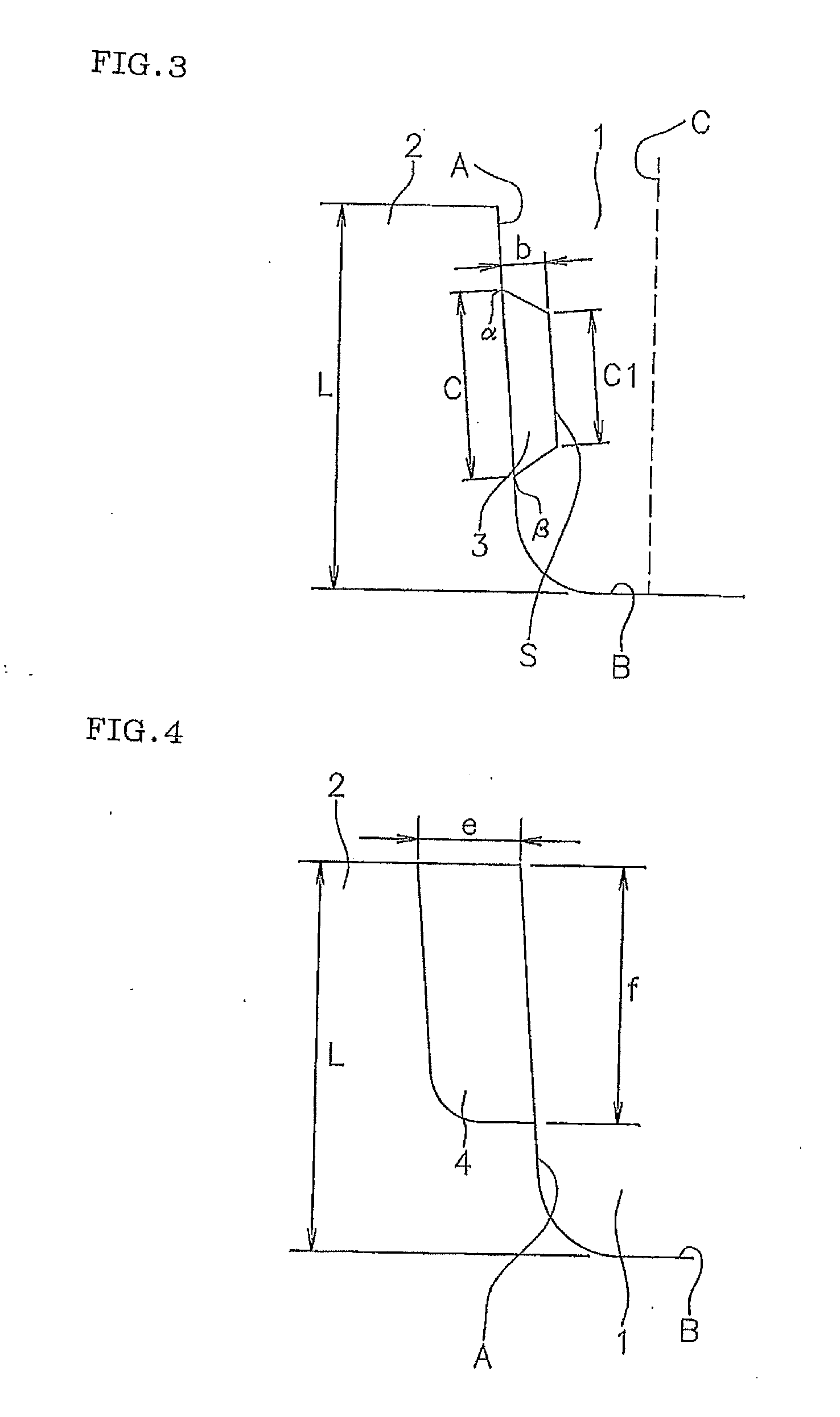
[0046]A pneumatic tire of Example 1 was prepared as described below. That is, the tread surface was formed with four main grooves 1 as illustrated in FIG. 1. Protruding portions 3 and sipes 4 were formed on both side wall surfaces A of the main grooves 1 as illustrated in FIGS. 2 to 4, in which the protruding portions 3 were formed being opposite to each other on the respective wall surfaces of the groove A as viewed in a groove width direction. (In the main groove 1, groove width W was 10 mm; depth of the groove L was 16.5 mm; width a of the protruding portion 3 was 8 mm; height “b” was 2 mm; length “c” in a depth direction was 8 mm; width “a1” of the flat plane S of the protruding portion 3 was 6 mm; length “c1” in a depth direction of the flat plane S was 6 mm; width “d” of the sipe 4 was 1 mm; length “e” was 4 mm; sipe depth “f” was 11 mm; distance “g” was 7 mm; and distance “i” was 15 mm). Measured values of the evaluation items are shown in Table 1.

example 2

[0047]A pneumatic tire of Example 2 has the same constitution as in Example 1, except that the protruding portions 3 formed on the respective wall surfaces of the groove A were disposed so as not to opposite to each other as viewed in a groove width direction. Measured values of the evaluation items are shown in Table 1.

Conventional Example

[0048]A pneumatic tire of Example 2 has the same constitution as in Example 1, except that protruding portions 3 and sipes 4 were not formed in the main grooves 1. Measured values of the evaluation items are shown in Table 1.


PUM


Abstract

An object of the present invention is to provide a pneumatic tire capable of, while restricting deformation of groove portions to prevent groove cracks, preventing chipping-off or break-off of protruding portions formed on wall surfaces of the groove as well as preventing irregular wear of the tire. In order to achieve the object, a pneumatic tire comprises a tread surface formed with a plurality of groove portions thereon, wherein at least one of the wall surfaces of the groove portion includes protruding portions and cut-off portions opened to the groove wall surface, and the protruding portions and the cut-off portions are formed alternately on the groove wall surface in an extending direction thereof.

Description

BACKGROUND OF THE INVENTION[0001]1. Field of the Invention[0002]The present invention relates to a pneumatic tire having a tread surface formed with a plurality of groove portions thereon.[0003]2. Description of the Related Art[0004]In order to enhance drainage performance, traction performance, braking performance or the like, pneumatic tires have a tread surface formed with a plurality of main grooves extending in a circumferential direction of the tire as well as a plurality of transverse grooves extending in a width direction of the tire. When brake is applied or while turning a vehicle, these groove portions are subjected to a large load causing a large deformation in a direction reducing the groove width. At this time, strain converges on the bottom of groove causing cracks (groove cracks). Thus, the deformation of tire may cause a problem in an aspect of the durability of the tire.[0005]As a technique to reduce convergence of strain on the bottom of groove, there is known a t...

Claims


Application Information

Patent Timeline
Patent Type & Authority Applications(United States)
IPC IPC(8): B60C11/117
CPCB60C11/0309B60C2011/133B60C2011/1338
Inventor YOKOMAKURA, SEIJI
Owner TOYO TIRE & RUBBER CO LTD
Why Eureka
Try Eureka