
Electronic flight bag mounting bracket

a technology for mounting brackets and flight bags, which is applied to machine supports, washstands, furniture parts, etc., can solve the problems of efb becoming damaged, efb being lost among other items in the cockpit, and the brackets used in class 2 and class 3 hardware typically do not permit easy removal of electronic equipmen

Active Publication Date: 2011-11-17
CARLISLE INTERCONNECT TECH
View PDF7 Cites 10 Cited by
  • Summary
  • Abstract
  • Description
  • Claims
  • Application Information

AI Technical Summary

Benefits of technology

Another aspect, that may be implemented either alone or in conjunction with the first aspect, permits one-handed operation of the mounting bracket, e.g., a user may adjust and secure the position of the mounting bracket using only one hand. A further aspect of the invention is to provide a single mechanism that both secures the position of the mounting assembly with respect to the track and that mounts the EFB on the mounting assembly.
A yet further aspect which, like the others, may be implemented either alone or in conjunction with one or more of the other aspects, is to provide a mounting bracket that has one or more of the characteristics discussed above but which is relatively simple and inexpensive to manufacture and assemble using a minimum of equipment.

Problems solved by technology

In the past, a pilot simply may have placed an EFB loosely within the cockpit of an airplane, e.g., on the floor, which may lead to problems during the flight.
For example, the EFB may become lost among other items in the cockpit, or the position of the EFB may shift during the flight.
Further, if there is turbulence, the EFB may become damaged if it is not secured within the cockpit.
Brackets used in Class 2 and class 3 hardware typically do not permit easy removal of the electronic equipment.
The orientation and / or position of the electronic equipment also cannot easily be changed to accommodate user preference.
Those brackets that do permit adjustment require considerable manipulation with both hands, which can be distracting and inconvenient for the pilot or other operator.

Method used


Image

  • Electronic flight bag mounting bracket
  • Electronic flight bag mounting bracket
  • Electronic flight bag mounting bracket

Examples


Embodiment Construction

The present invention and the various features and advantageous details thereof are explained more fully with reference to the non-limiting embodiments described in detail in the following description.

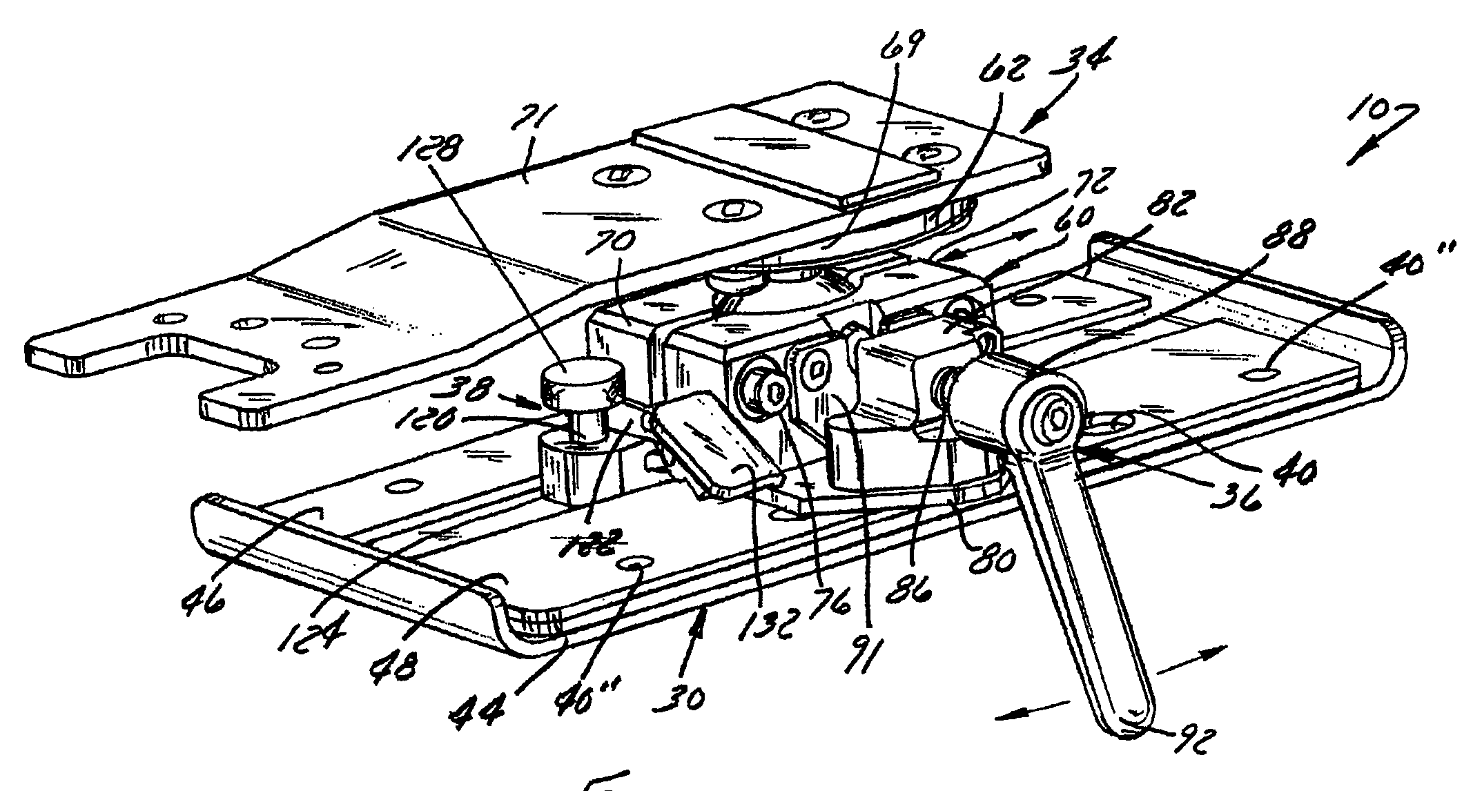
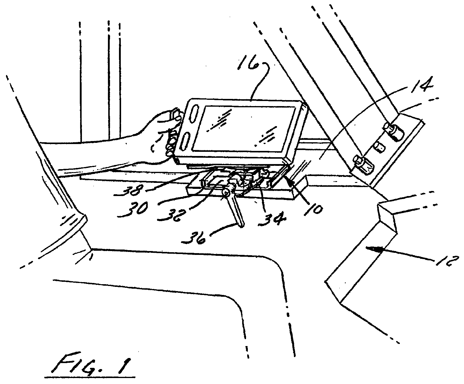
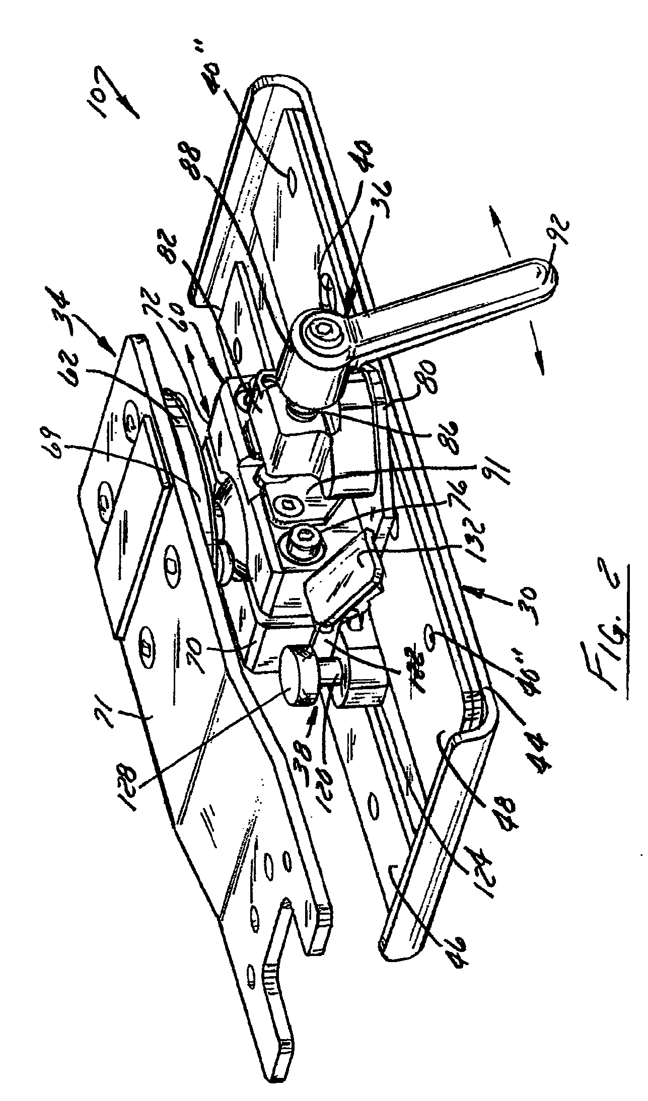
As shown in FIG. 1, the mounting bracket 10 is mounted in a cockpit 12 of an airplane, preferably on a substrate 14 such as a ledge or other location that is easily accessible by a seated pilot. Mounting bracket 10 generally comprises a frame 30 with a track 32 and a mounting assembly 34 that is configured to slidably engage the track 32. First and second positioning mechanisms 36 and 38 provide continuous and discrete positioning, respectively, of the mounting assembly 34 along the track 32.

The size and shape of the frame 30 may vary, but it preferably is generally rectangular in shape with the track 32 spanning the length of the rectangle to allow for a greater number of potential positions for the mounting assembly with respect to the track. The dimensions of the frame 30 may vary b...


PUM


Abstract

A mounting bracket for an electronic flight bag (EFB) includes a frame having a track and a mounting assembly that is having a base and a support that is moveably connected to the base and can be selectively fixed in position on the track. The mounting bracket may allow for singlehanded adjustment of the position of the mounting assembly with respect to track at one of at least two discrete locations along the track, or at any desired position along the track. Further, the mounting bracket may provide a single mechanism for both securing the EFB to the mounting assembly and orienting the support with respect to the base.

Description

BACKGROUND OF THE INVENTION1. Field of the InventionThe present invention relates in general to a mounting bracket for an electronic display device such as an electronic flight bag (EFB).2. Discussion of the Related ArtAn EFB is an electronic display device that a pilot may use for preflight check lists and similar activities. EFB's are generally handheld, portable devices that a pilot can take from flight to flight. Information regarding a pilot's flight or flights may be preloaded onto the EFB so that the pilot may access it prior to, during and after the flight.In the past, a pilot simply may have placed an EFB loosely within the cockpit of an airplane, e.g., on the floor, which may lead to problems during the flight. For example, the EFB may become lost among other items in the cockpit, or the position of the EFB may shift during the flight. Further, if there is turbulence, the EFB may become damaged if it is not secured within the cockpit.Partially in response to these concerns...

Claims


Application Information

Patent Timeline
IPC IPC(8): A47B96/06
CPCB64D43/00B64D2045/0075F16M2200/022F16M13/02F16M11/14F16M11/2085
Inventor DEBUHR, MERRITTEBITANT, JEFFREYRICHARDS, DANIEL
Owner CARLISLE INTERCONNECT TECH
Learn More