Radio base station, radio terminal, and radio communication method

a radio terminal and radio communication technology, applied in the field of radio terminals, radio base stations, radio communication methods, can solve the problems of insufficient improvement of communication quality, achieve the effect of preventing the occurrence of interference signals, improving cell throughput, and improving communication quality in the radio terminal ue1

Active Publication Date: 2011-11-17
KYOCERA CORP
View PDF2 Cites 44 Cited by
  • Summary
  • Abstract
  • Description
  • Claims
  • Application Information

AI Technical Summary

Benefits of technology

[0144]With the radio communication system 1010A according to the first embodiment, in a case where the radio terminals UE1 to UE3 receive the second radio signals from the radio base station BS2 as the interference signals, the null points in the radio base station BS2 are directed to the directions D1 to D3 of the radio terminals UE1 to UE3, respectively. Thus, the radio terminal UE1 can avoid receiving the second radio signal (interference signal), and the communication quality in the radio terminal UE1 can be improved sufficiently. Accordingly, the prevention of occurrence of the interference signals in the source makes it possible to provide high-speed downlink communications to each of the radio terminals while increasing the cell throughput.
[0145]In the first embodiment, the transmission directivity controller 1422 of the radio base station BS2 transmits the second radio signal while directing the null points to the directions D1 to D3 of the radio terminals UE1...

Problems solved by technology

For this reason, there has been a problem that the communication quality cannot be i...

Method used


Image

  • Radio base station, radio terminal, and radio communication method
  • Radio base station, radio terminal, and radio communication method
  • Radio base station, radio terminal, and radio communication method

Examples


first embodiment

[0058]In the first embodiment, a description will be given of (1) Summary of Radio Communication System 1010A, (2) Detailed Configuration of Radio Communication System 1010A, (3) Transmission Directivity Control in Radio Base Station BS2, (4) Operation of Radio Communication System, and (5) Effects.

(1) Summary of Radio Communication System 1010A

[0059]A description will be given of a summary of a radio communication system 1010A in the order of (1.1) Schematic Configuration of Radio Communication System 1010A and (1.2) Schematic Operation of Radio Communication System 1010A.

(1.1) Schematic Configuration of Radio Communication System 10A

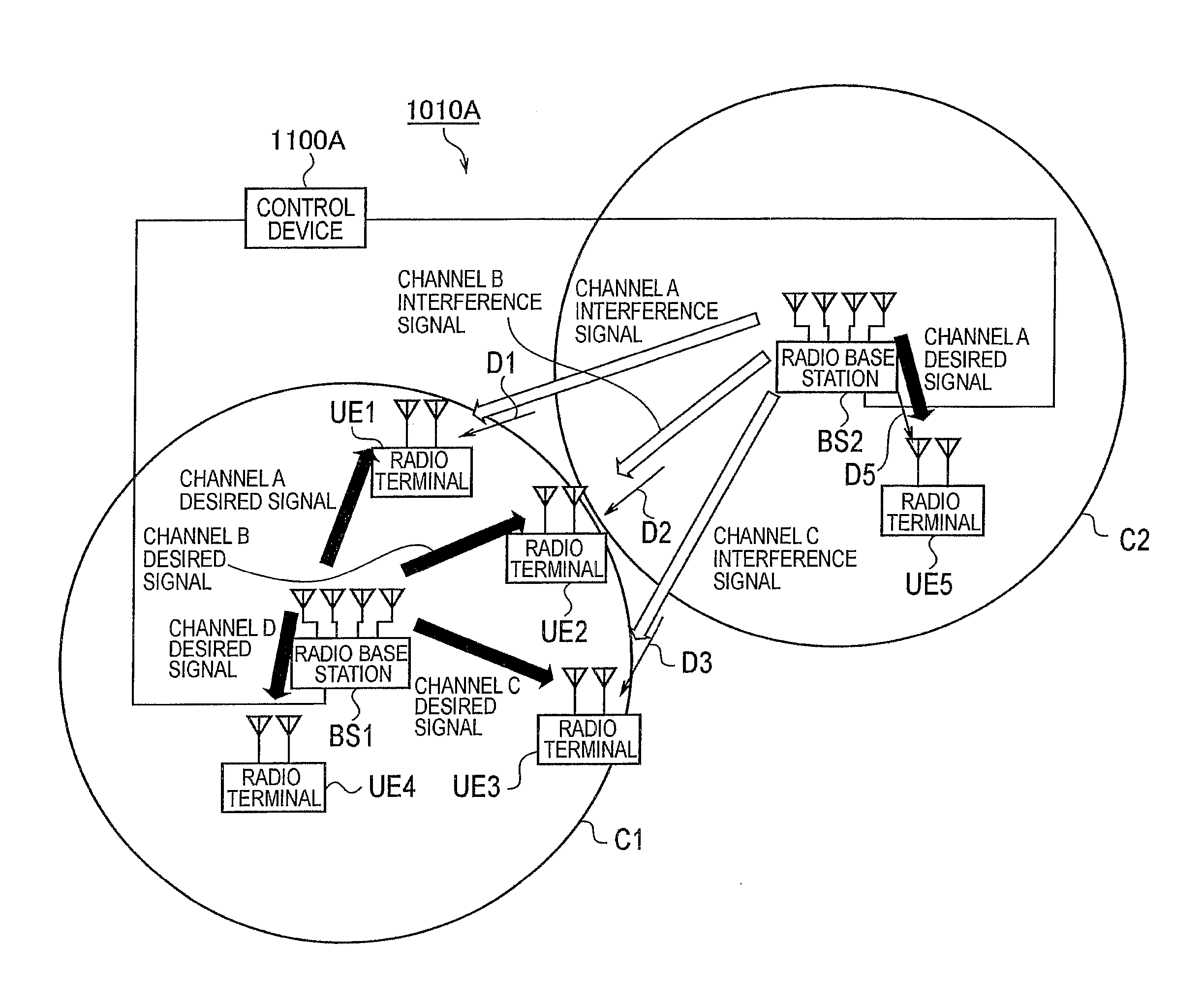
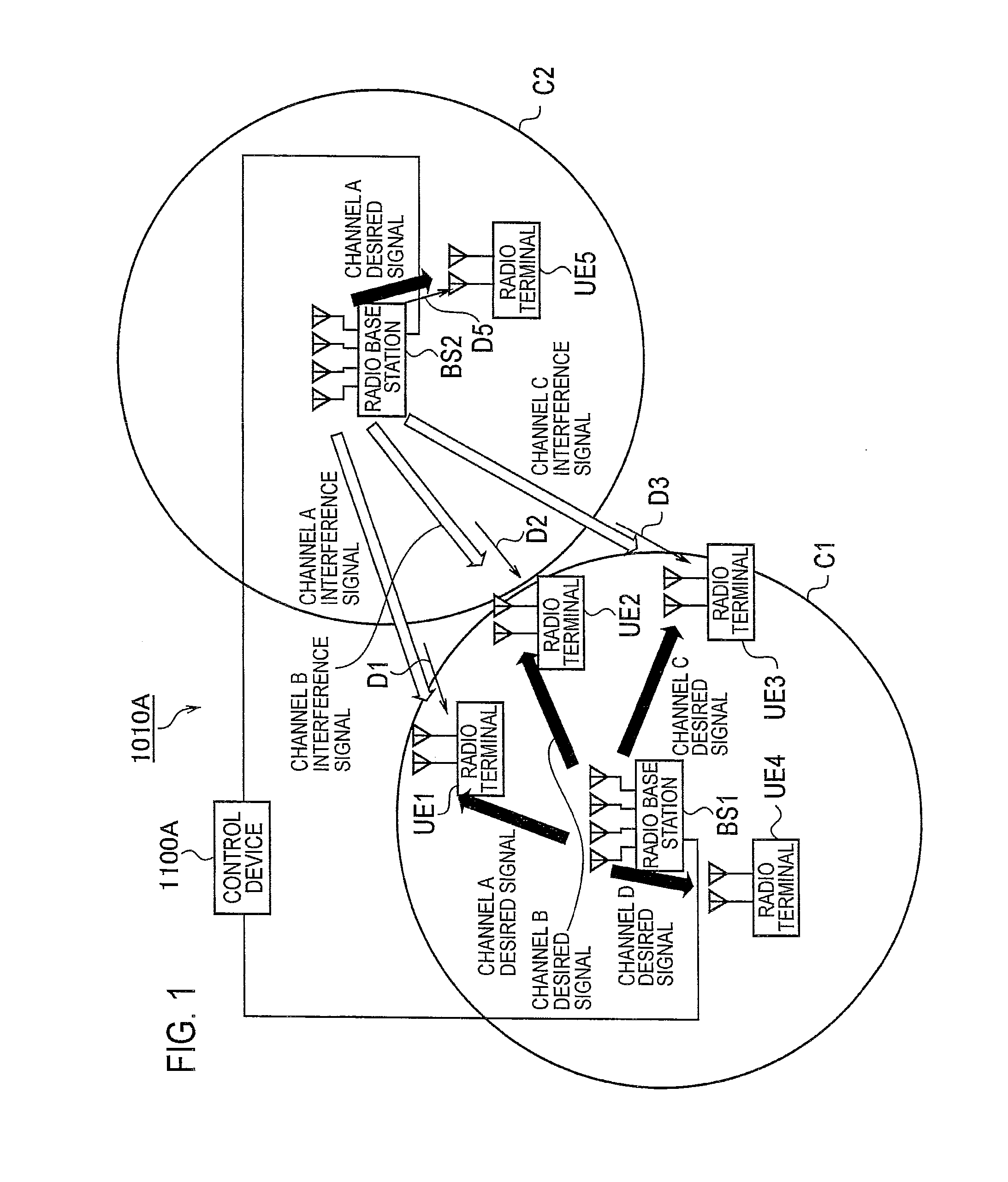
[0060]FIG. 1 is an overall configuration diagram of the radio communication system 1010A according to the first embodiment.

[0061]As shown in FIG. 1, the radio communication system 1010A includes a radio terminal UE1, a radio terminal UE2, a radio terminal UE3, a radio terminal UE4, a radio terminal UE5, a radio base station BS1 (first radio base statio...

modification example 1 of first embodiment

[0147]In the aforementioned first embodiment, the interference source identification unit 1121 of the control device 1100A identifies the radio base station BS2 of the interference source from among multiple radio base stations on the basis of the radio base station identification information, but it is also possible to identify the interference source by use of the following method.

[0148]In this modification example, the storage unit 1130 of the control device 1100A previously holds therein correspondence information associating interference information with each of the radio base stations. The interference source identification unit 1121 of the control device 1100A identifies the radio base station BS2 of the interference source from among multiple radio base stations on the basis of the interference information received by the receiver 1111 and the correspondence information held in the storage unit 1130.

[0149]According to the aforementioned method, the base station identificatio...

modification example 2 of first embodiment

[0150]In the aforementioned first embodiment, the information indicating the coefficient or angle indicating the arrival direction, or the PMI is used as the interference information and the control information.

[0151]However, location information indicating the location of each of the radio terminals UE1, UE2 and UE3 may be used as the interference information and the control information. In this case, an existing location detection technique such as location detection using a GPS can be used. In a case where the location information is used as the interference information and the control information, the transmission directivity controller 422 of the radio base station BS2 may identify the respective directions of the radio terminals UE1, UE2 and UE3 from the respective locations of the radio terminals UE1, UE2 and UE3.


PUM


Abstract

A radio base station (BS2) comprises: a transmitter (1412) that transmits, via a plurality of transmission antennas, a radio signal to a first radio terminal having a plurality of reception antennas; a transmission directivity controller (1422) that controls directional beam, which is formed by the transmission antennas, on the basis of feedback information that is fed back from the first radio terminal; and an information acquiring unit (1421) that acquires control information to be used for directing the null points of the directional beam toward a second radio terminal that receives, as an interference signal, the foregoing radio signal during communication with another radio base station. The transmission directivity controller (1422) directs, based on the feedback information and control information, the directional beam toward the first radio terminal and the foregoing null points toward the second radio terminal.

Description

TECHNICAL FIELD[0001]The present invention relates to a radio base station, a radio terminal, and a radio communication method, all of which uses a multiple-antenna technique.BACKGROUND ART[0002]In recent years, for efficiently utilizing a limited frequency band, radio communication systems have been using multiple-antenna techniques with which at least one of a transmission side and a reception side uses multiple antennas. One of known multiple-antenna techniques is for multiple-input multiple-output (MIMO) communications in which multiple signal sequences using the same frequency are simultaneously transmitted via multiple transmission antennas and then received via multiple reception antennas, and then, the received signal sequences are demultiplexed from each other.[0003]The MIMO communications include a scheme in which the reception side estimates propagation channel characteristics between the reception side and the transmission side and then feeds back feedback information ba...

Claims


Application Information

Patent Timeline
IPC IPC(8): H04W4/00
CPCH04B7/024H04W88/08H04W72/046
Inventor TANAKA, TAKANORI
Owner KYOCERA CORP
Why Eureka
Try Eureka