
Pulse wave analyzer and pulse wave analyzing method

a pulse wave and analyzer technology, applied in the field of pulse wave analyzers and pulse wave analyzing methods, can solve the problems of difficult application of pulse wave measurement techniques to the upper arm that can be measured at home, difficult to accurately extract the rising point of the reflection point from the synthetic wave, and difficult to achieve the effect of automatic analysis

Inactive Publication Date: 2011-11-17
OMRON HEALTHCARE CO LTD
View PDF6 Cites 7 Cited by
  • Summary
  • Abstract
  • Description
  • Claims
  • Application Information

AI Technical Summary

Benefits of technology

The present invention provides a pulse wave analyzer and a pulse wave analyzing method capable of extracting a convergence time of the reflection wave and calculating the index useful in the diagnosis of heart disease. This is achieved by detecting a pulse wave and carrying out a process based on the pulse wave, including extracting a characteristic point for sectionalizing a reflection wave zone from a pulse wave waveform of one beat and calculating the convergence time of the reflection wave as an index. This allows for the accurate analysis of pulse waves and the diagnosis of heart disease.

Problems solved by technology

However, the rising point of the reflection point is difficult to be accurately extracted from the synthetic wave, and in particular, the rising point of the reflection wave may be hard to appear in the synthetic wave depending on the measuring site.
Non-patent document 1 relates to a technique of capturing a different phenomenon and calculating the index, but the technique is difficult to apply to the pulse wave measured at the upper arm that can be measured at home.

Method used


Image

  • Pulse wave analyzer and pulse wave analyzing method
  • Pulse wave analyzer and pulse wave analyzing method
  • Pulse wave analyzer and pulse wave analyzing method

Examples


Embodiment Construction

[0027]Embodiments of the present invention will be hereinafter described with reference to the drawings. In the following description, the same reference numerals are denoted for the same components and configuring elements. The names and functions thereof are also the same.

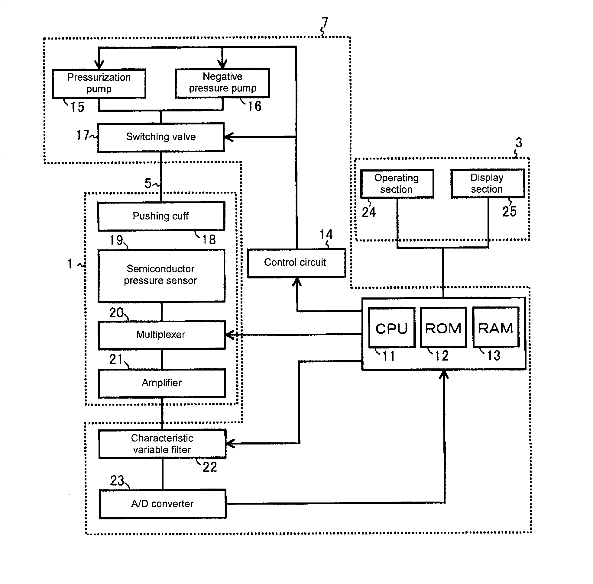
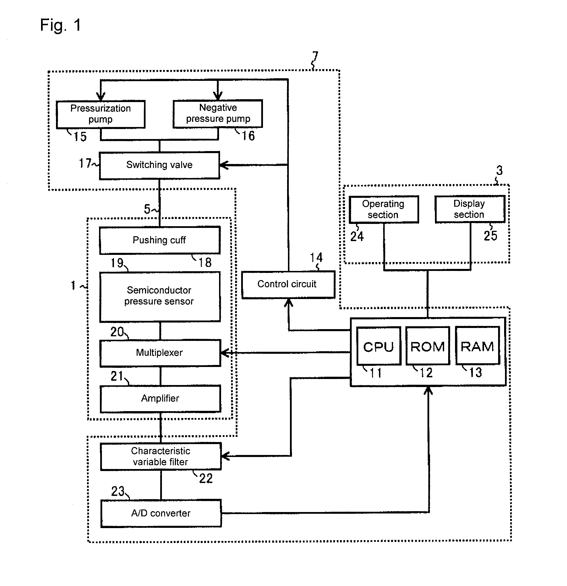
[0028]With reference to FIG. 1, a pulse wave analyzer according to one or more embodiments of the present invention includes a sensor unit 1, a display unit 3, and a fixing stand unit 7.

[0029]The display unit 3 includes an operating section 24 arranged to be operable from the outside so as to be operated to input various types of information related to pulse wave analysis or the like, and a display section 25 including an LED (Light Emitting Diode) or an LCD (Liquid Crystal Display) for outputting various types of information such as the pulse wave analysis result to the outside.

[0030]The fixing stand unit 7 includes a ROM (Read Only Memory) 12 and a RAM (Random Access Memory) 13 for storing data and programs for...


PUM


Abstract

In a pulse wave analyzer, a local maximum point of a fourth order differentiated wave of the pulse wave of one beat is acquired, and a maximum point of a reflection wave of the local maximum points of the fourth order differentiation existing in a zone of an original waveform is determined as a starting point of a reflection wave zone that is a first characteristic point. With 10% of the amplitude of the first characteristic as a threshold value, a time point at which the amplitude reaches the threshold value after the relevant point is determined as an ending point of the reflection wave zone that is a second characteristic point. The duration time of the reflection time of the time between the first characteristic point and the second characteristic point is calculated as an index useful in the diagnosis of heart disease.

Description

TECHNICAL FIELD[0001]The present invention relates to pulse wave analyzers and pulse wave analyzing methods, and in particular, to a pulse wave analyzer and a pulse wave analyzing method for calculating a characteristic point of a pulse wave.BACKGROUND ART[0002]One of the information useful in diagnosing cardiovascular disease such as arterial sclerosis is the transmission timing or the occupying time of the reflection wave in the pulse wave. In order to obtain the time where the reflection wave in the pulse wave exists, an analysis for dividing the measured pulse wave to the range of ejection wave and the range of reflection wave is required.[0003]In Japanese Unexamined Patent Publication No. 2005-349116 (hereinafter referred to as patent document 1), the applicant of the present application proposes a pulse analyzer for extracting a characteristic point of a pulse wave, and calculating an index such as an Al (Augmentation Index) or a TR (Traveling time to Reflected wave). The inde...

Claims


Application Information

Patent Timeline
Patent Type & Authority Applications(United States)
IPC IPC(8): A61B5/02
CPCA61B5/022A61B5/7239A61B5/7207A61B5/021A61B5/02108A61B5/02116A61B5/02125A61B5/02416A61B5/0245A61B5/0285A61B5/7235A61B5/725
Inventor SATO, HIRONORIKOBAYASHI, TATSUYAYOSHIDA, HIDEAKIFUJII, KENJIOGURA, TOSHIHIKO
Owner OMRON HEALTHCARE CO LTD
Learn More