
Heavy particle oil separator splash shield

a technology of heavy particle oil and splash shield, which is applied in the direction of auxilary lubrication, lubrication elements, pressure lubrication with lubrication pump, etc., can solve the problem of reducing the efficiency of the element of the oil separator, and achieve the effect of reducing exhaust particulate emissions, minimizing the saturation of the oil separator, and minimizing the droplet of heavy particle oil

Inactive Publication Date: 2011-11-24
ELECTRO-MOTIVE DIESEL
View PDF3 Cites 2 Cited by
  • Summary
  • Abstract
  • Description
  • Claims
  • Application Information

AI Technical Summary

Benefits of technology

[0007]The present disclosure generally relates to a locomotive diesel engine and, more particularly, to a heavy particle oil separator splash shield. Specifically, provided is a system and method for reducing exhaust particulate emissions. The present shield minimizes heavy particle oil droplets from the cam shaft drive gears from entering the oil separator. As a result, the present shield minimizes saturation of the oil separator, thereby increasing the efficiency of the oil separator and reducing environmental pollution.

Problems solved by technology

Therefore, additional oil splashed into the separator from the cam shaft drive gears decreases the efficiency of the element of the oil separator, thus allowing more particulate matter to be released into the atmosphere.

Method used


Image

  • Heavy particle oil separator splash shield
  • Heavy particle oil separator splash shield
  • Heavy particle oil separator splash shield

Examples


Embodiment Construction

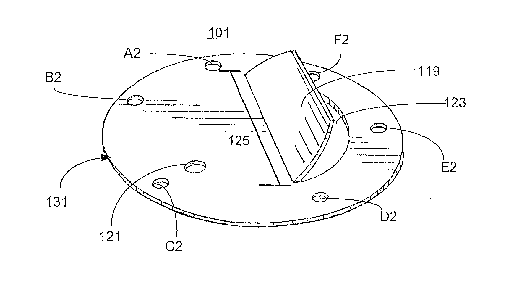
[0021]The present disclosure relates to reduction in exhaust particulate emissions from a locomotive diesel engine, and specifically to a heavy particle oil separator splash shield. The oil splash shield reduces the amount of heavy particle oil splashed from a cam shaft drive gear into the oil separator, thereby reducing engine exhaust particulate matter emissions.

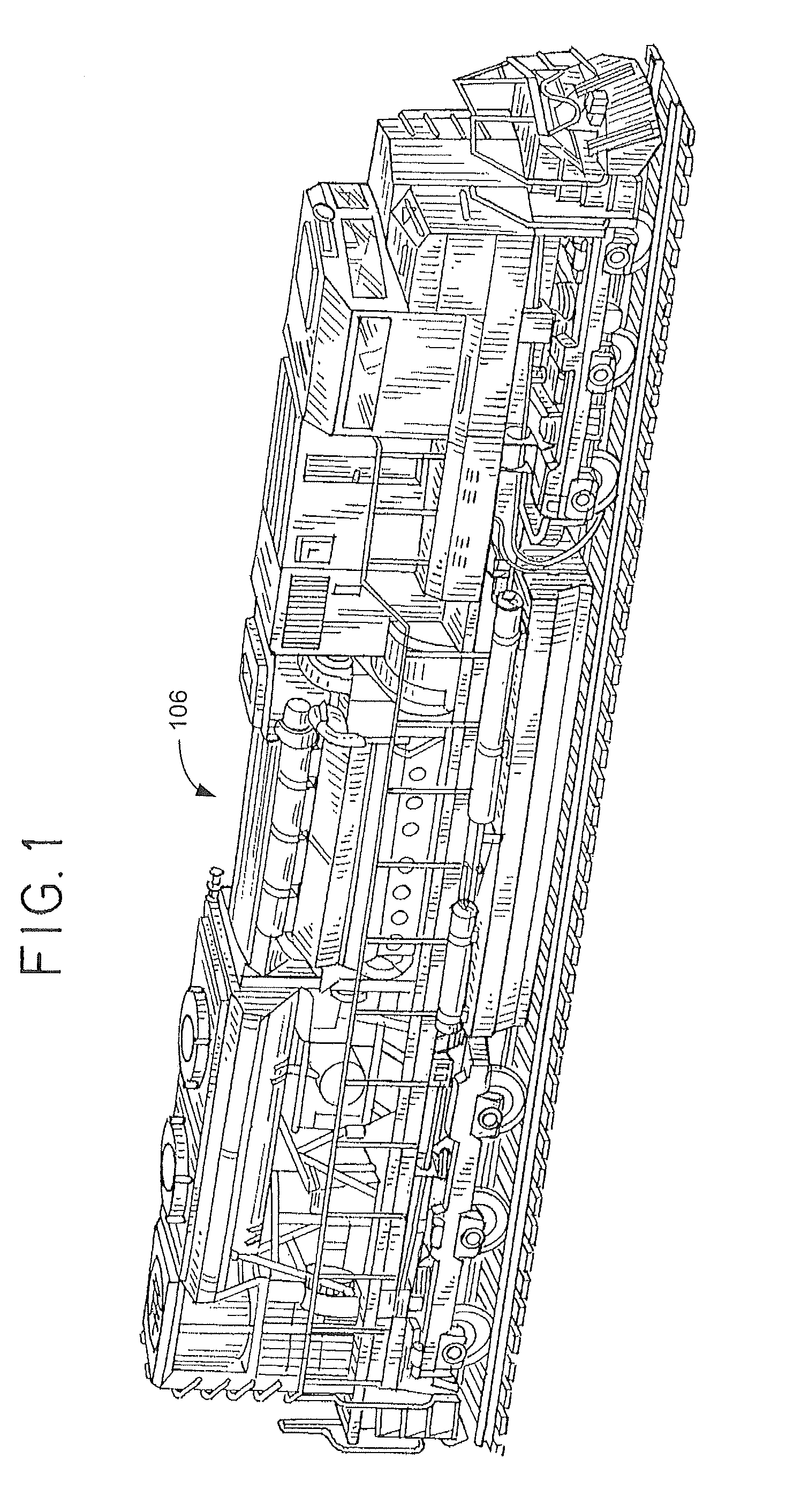
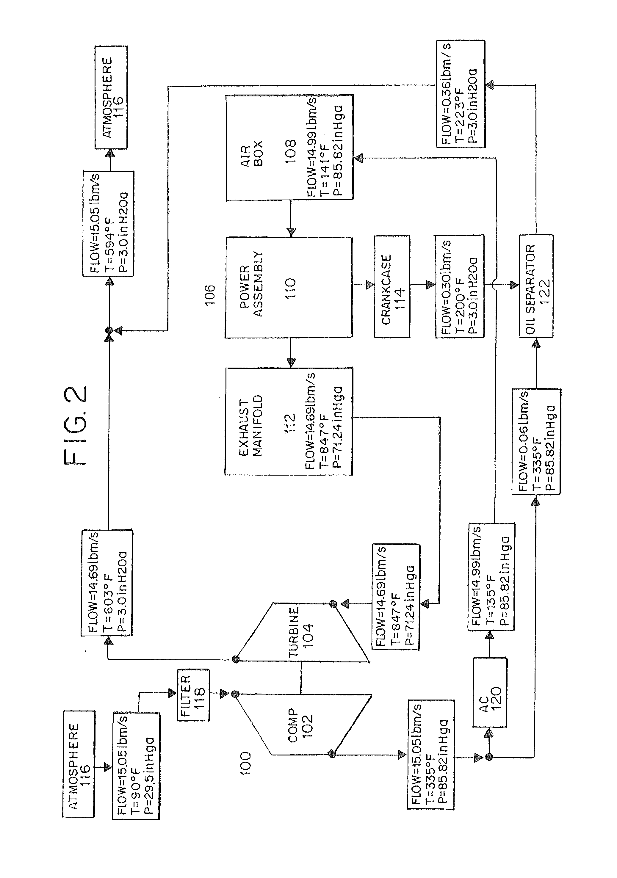
[0022]FIGS. 1-3 illustrate the present locomotive diesel engine generally comprising a turbocharger 100 having a compressor 102 and a turbine 104 which provides compressed air to an engine 106 having an airbox 108, power assembly 110, an exhaust manifold 112, and a crankcase 114. In a typical locomotive diesel engine, the turbocharger 100 increases the power capability of the engine 106 by pressurizing and increasing the amount of air transferred to the engine 106. More specifically, the turbocharger 100 draws air from the atmosphere 116 which is filtered using a conventional air filter 118. The filtered air is pressurized...


PUM

PropertyMeasurementUnit
lengthaaaaaaaaaa
combustibleaaaaaaaaaa
power capabilityaaaaaaaaaa

Abstract

The present disclosure generally relates to a locomotive diesel engine and, more particularly, to a heavy particle oil separator splash shield. Specifically, provided is a system and method for reducing exhaust particulate emissions. The present shield minimizes heavy particle oil droplets in close proximity to the oil separator from entering the filter. As a result, the present shield minimizes saturation of the oil separator, thereby increasing the efficiency of the oil separator and reducing environmental pollution.

Description

CROSS-REFERENCE TO RELATED APPLICATIONS[0001]This application is a Nonprovisional Patent Application, which claims benefit to U.S. Provisional Application Ser. No. 61 / 346,091, entitled “Heavy Particle Oil Separator Splash Shield,” filed May 19, 2010, the complete disclosure thereof being incorporated herein by reference.BACKGROUND OF THE DISCLOSURE[0002]The present disclosure relates to reduction in exhaust particulate emissions from a locomotive diesel engine, and specifically to a heavy particle oil separator splash shield.[0003]Oil separators are designed to trap and recover small oil droplets and particulate matter from vapors emitted from engines. Specifically, the crankcase ventilation oil separator is used to prevent the build-up of combustible gases in the crankcase, by collecting oil and particulate matter from vapors.[0004]Cam shaft drive gears and counterweights are generally located in close proximity to the passage leading to the oil separator. The cam shaft drive gears...

Claims


Application Information

Patent Timeline
Patent Type & Authority Applications(United States)
IPC IPC(8): F01M11/00B23P17/00
CPCF01M13/04Y10T29/49229F01M2013/0433
Inventor DEVOS, DALE A.GOETZKE, MICHAEL B.
Owner ELECTRO-MOTIVE DIESEL
Learn More