Air pump

a technology of electromagnetic radiation and air pump, which is applied in the direction of piston pumps, positive displacement liquid engines, pump parameters, etc., can solve the problems of inability to efficiently dissipate heat generated in the tank and inability to easily transmit heat of the air tank to the pump unit, and achieve efficient dissipation, convenient disassembly and reassembling, and satisfactory sealing properties.

Active Publication Date: 2011-11-24
NITTO KOHKI CO LTD
View PDF12 Cites 2 Cited by
  • Summary
  • Abstract
  • Description
  • Claims
  • Application Information

AI Technical Summary

Benefits of technology

[0013]In this air pump, the resinous tank body is put between the metallic bottom wall member and a metallic part of the pump unit, and bolts are passed through from the bottom wall member and into the metallic part of the pump unit and tightened to securely connect the pump unit and the air tank to each other. Therefore, the resinous tank body can be firmly and easily secured to the pump unit with satisfactory sealing properties between the bottom wall member and the tank body. Accordingly, the tank body can be prevented from becoming deformed even if the air pump is used for a long period of time. In addition, disassembling and reassembling are easy when maintenance is performed on the air pump.
[0014]In addition, heat generated in the tank can be efficiently dissipated through the metallic bottom wall member, and the air pump can be made so that the heat of the air tank is not easily transmitted to the pump unit.
[0015]Specifically, the peripheral wall may have a double-wall structure comprising an outer wall, an inner wall, and at least one air gap between the outer and inner walls. The double-wall structure suppresses the transmission of vibration noise of air from the air tank to the outside.
[0016]Specifically, the at least one air gap may comprise a plurality of air gaps spaced from each other in the circumferential direction of the peripheral wall, and an intermediate wall may be provided between adjacent air gaps to connect together the outer and inner walls. This is for attaining a noise reduction effect of the peripheral wall and for maintaining the strength of the peripheral wall.
[0017]Further, the arrangement may be as follows. The tank body has a partition wall extending downward from the top wall thereof to partition the interior of the tank body into a plurality of spaces. The partition wall has an air passage formed therein to allow air introduced into the air tank to flow toward an air outlet of the air pump through the plurality of spaces. The partition wall is shorter in height than the peripheral wall. Between the partition wall and the bottom wall member is provided a seal member that is more pliable than the resin used to form the tank body. The reason why a partition wall with an air passage is provided is to reduce the pulsation of air discharged from the air tank. The reason why the partition wall is shorter than the peripheral wall and a relatively pliable seal member is provided is as follows. If the partition wall has the same height as that of the peripheral wall and is abutted directly against the bottom wall member to seal therebetween, sealing cannot be completed unless the lower surface of the peripheral wall and the lower surface of the partition wall are completely flush with each other. Consequently, the production process becomes difficult. For this reason, a relatively pliable seal member is interposed between the partition wall and the bottom wall member to allow the desired sealing to be attained even if the respective lower surfaces of the partition wall and the peripheral wall are not completely flush with each other. In addition, it is possible to obtain the effect of suppressing vibration transmitted from the pump unit to the bottom wall member by the arrangement in which the partition wall is not abutted directly against the bottom wall member, but a seal member more pliable than the partition wall is interposed between the partition wall and the bottom wall member.
[0019]In this case, the seal member may be a sheet-shaped member stacked on the inner surface of the bottom wall member so that the inner wall and the partition wall sealingly engage with the seal member. Provision of the seal member stacked on the inner surface of the bottom wall member makes it difficult for the pulsation of air entering the air tank to be transmitted to the bottom wall member.

Problems solved by technology

In addition, heat generated in the tank can be efficiently dissipated through the metallic bottom wall member, and the air pump can be made so that the heat of the air tank is not easily transmitted to the pump unit.

Method used


Image

  • Air pump
  • Air pump
  • Air pump

Examples


Embodiment Construction

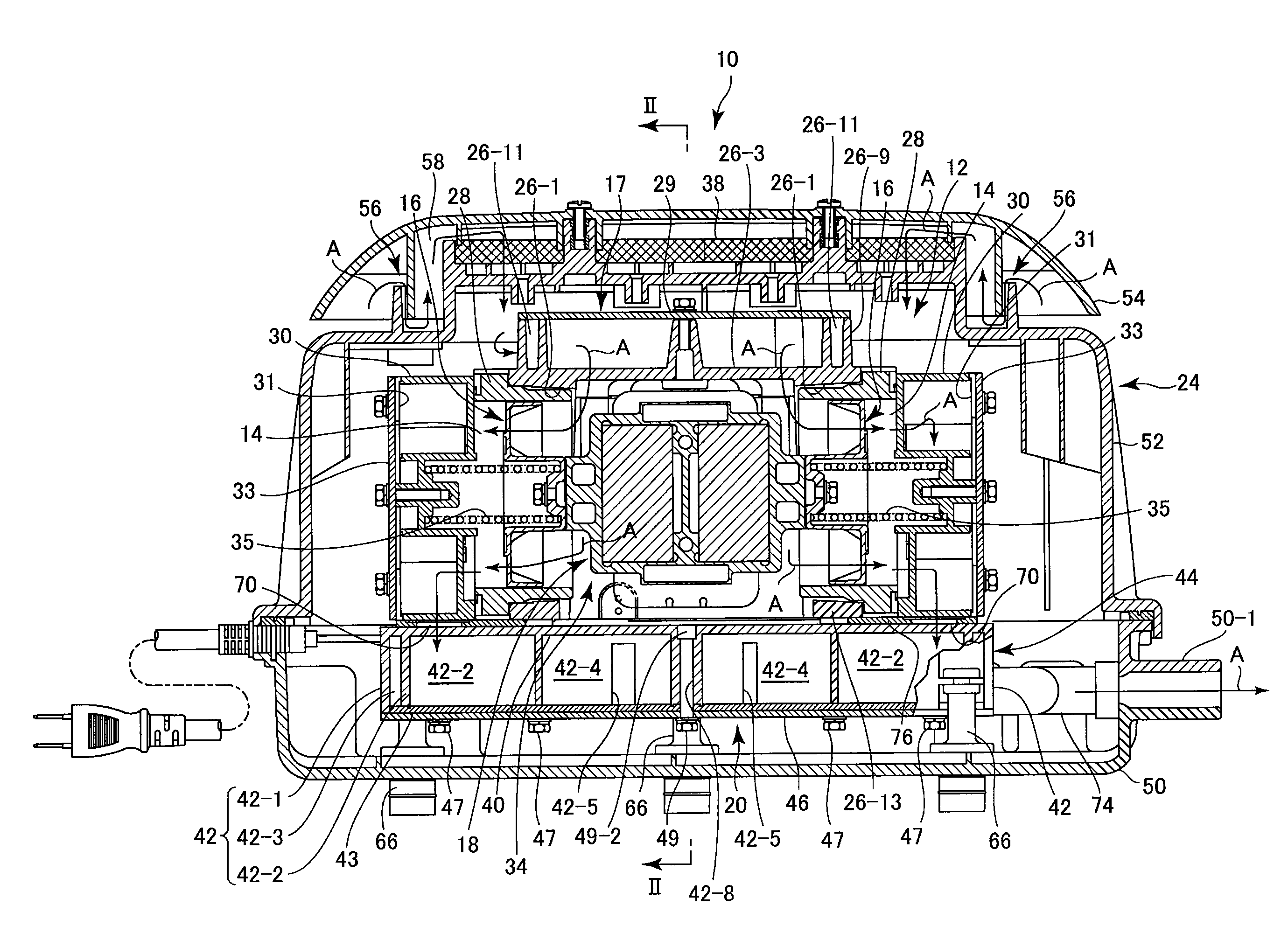
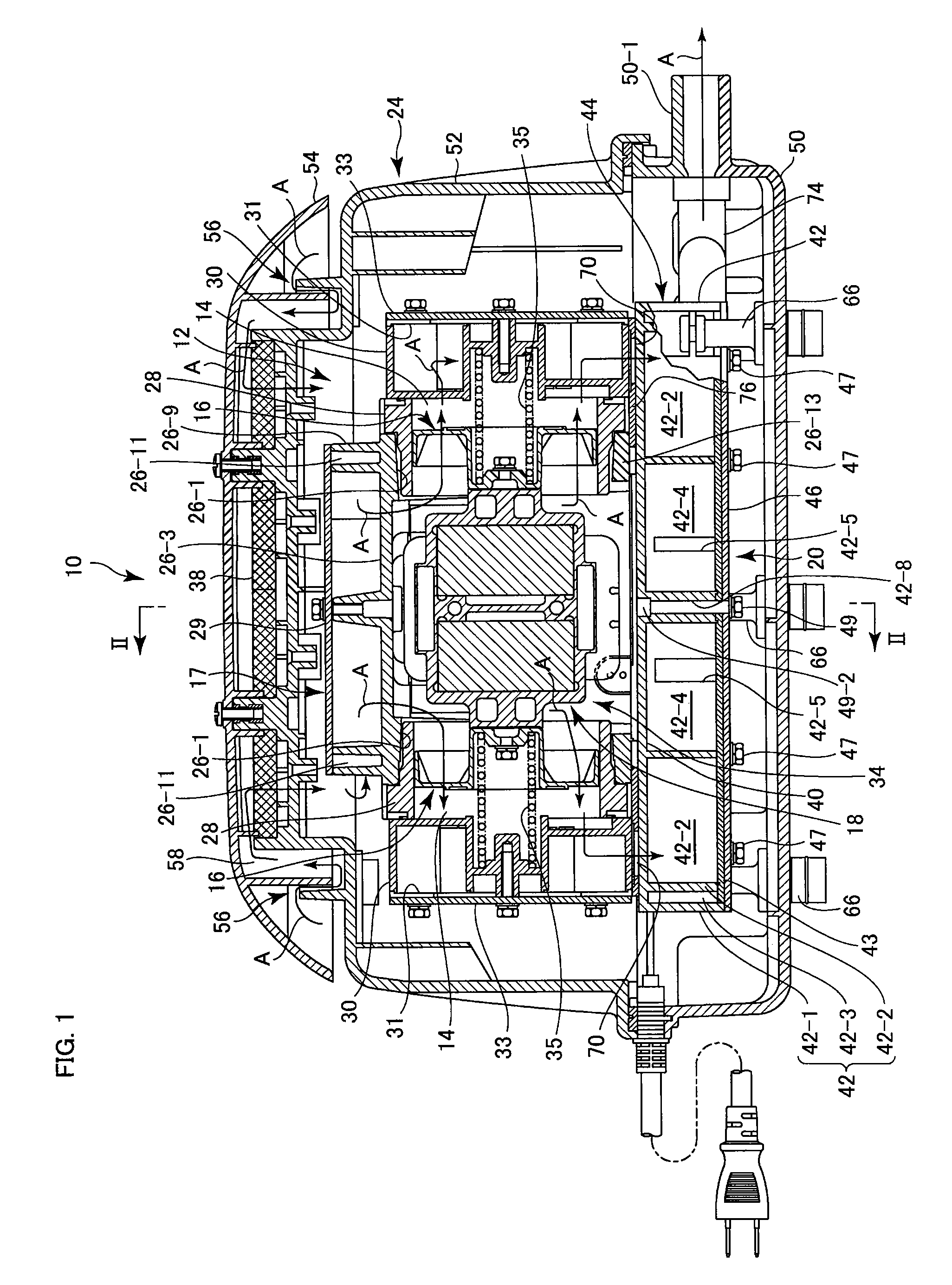
[0037]As illustrated in the figures, an air pump 10 according to the present invention has a pump unit 12 for sucking in and compressing air from the surroundings and an air tank 20 for temporarily storing the compressed air from the pump unit 12 to suppress pulsation caused by reciprocating motion of pistons 16 of the pump unit 12 before discharging the compressed air. The air pump 10 further has a housing 24 accommodating the pump unit 12 and the air tank 20.

[0038]First, these constituent elements and the overall structure will be outlined below.

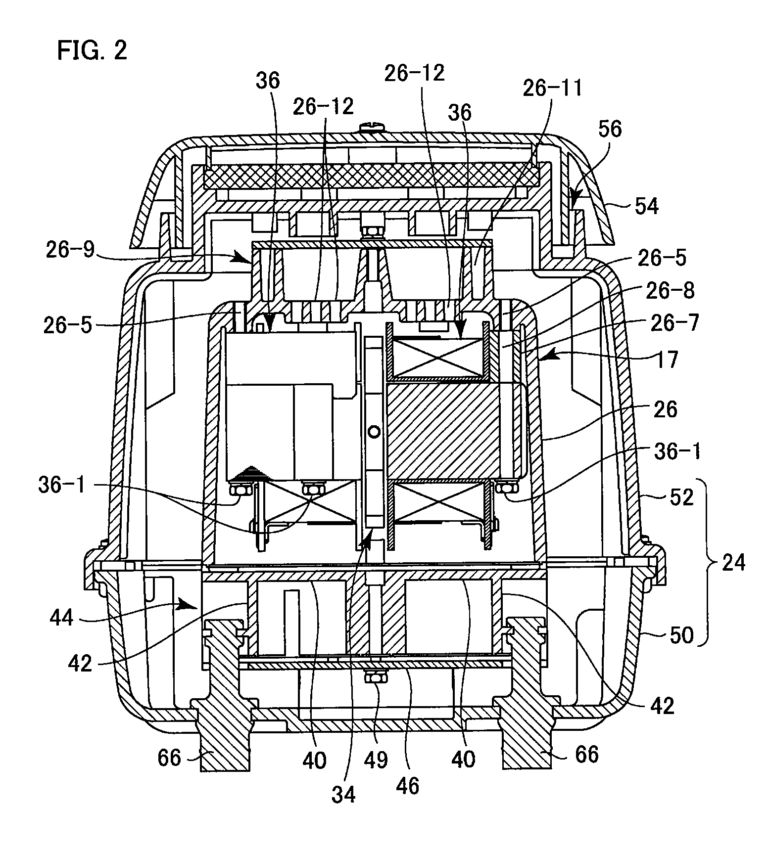
[0039]First, the pump unit 12 has a casing 17 having a pair of cylinder chambers 14 disposed in bilateral symmetry as seen in FIG. 1 to accommodate the pistons 16, respectively. The pump unit 12 further has an electromagnetic drive unit 18 reciprocating the two pistons 16 in the state of the two pistons being connected to each other. Specifically, the casing 17 has, as shown in FIGS. 2 to 5, a casing body 26 having a box shape as a whole a...


PUM


Abstract

An air pump has an air tank (20) for temporarily storing air from a pump unit (12) before discharging the air. The air tank has a tank body having a top wall (40) on which the pump unit is placed, and a peripheral wall (42) extending downward from the top wall. The tank body has a downward facing opening. The air tank further has a metallic bottom wall member (46) engaged with the bottom surface of the peripheral wall so as to close the opening of the tank body. Bolts are passed through the metallic bottom wall member and into a metallic part of the pump unit and tightened to connect and secure the pump unit and the air tank to each other.

Description

RELATED APPLICATIONS[0001]This application is a continuation of PCT / JP2010 / 051234 filed on Jan. 29, 2010, which claims priority to Japanese Application No. 2009-019849 filed on Jan. 30, 2009. The entire contents of these applications are incorporated herein by reference.BACKGROUND OF THE INVENTION[0002]1. Field of the Invention[0003]The present invention relates to electromagnetic air pumps and, more particularly, to an electromagnetic air pump having a resinous air tank for temporarily storing compressed air.[0004]2. Description of the Related Art[0005]An electromagnetic air pump has a pump unit having an electromagnetic drive section to suck in air from the surroundings and to compress the air and an air tank for temporarily storing the compressed air from the pump unit to remove pulsation caused in the compressed air by the pump unit before discharging the compressed air.[0006]Air compressed by the air pump is heated to a considerably high temperature by adiabatic compression. Th...

Claims


Application Information

Patent Timeline
Patent Type & Authority Applications(United States)
IPC IPC(8): E03B5/00
CPCF04B39/121F04B39/06F04B39/12F04B41/02F04B2201/0801Y10T137/86051Y10T137/86212
Inventor ISHIBASHI, SHIGEMITSUHASHIMOTO, ATSUKI
Owner NITTO KOHKI CO LTD
Why Eureka
Try Eureka