
Sealing rubber composition and seal member

a technology of composition and seal, applied in the field of sealing rubber, can solve the problem of bulky artificial graphite, and achieve the effect of reducing friction

Inactive Publication Date: 2019-08-13
JTEKT CORP +1
View PDF28 Cites 0 Cited by
  • Summary
  • Abstract
  • Description
  • Claims
  • Application Information

AI Technical Summary

Benefits of technology

The invention provides a new sealing rubber composition that has low friction, good sealing properties, and is resistant to wear and tear. The use of this composition in making a seal member helps to reduce friction and improve its longevity.

Problems solved by technology

The artificial graphite is bulky and is manufactured by firing a coke formed of petroleum, coal, or the like and graphitizing the coke at a high temperature.

Method used


Image

  • Sealing rubber composition and seal member
  • Sealing rubber composition and seal member
  • Sealing rubber composition and seal member

Examples


Embodiment Construction

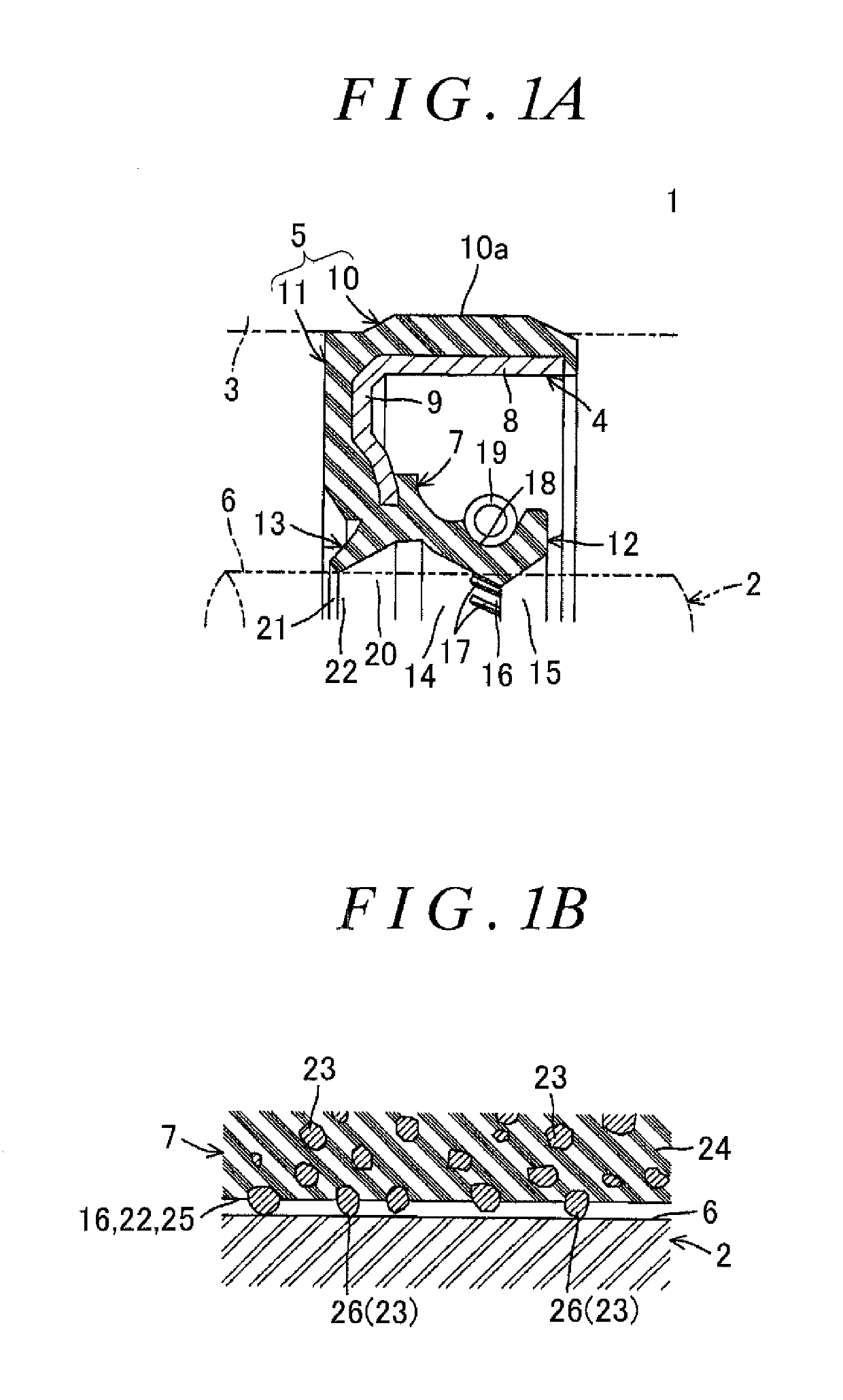
[0031]FIG. 1A is a sectional view showing an oil seal that is an example of a seal member according to an embodiment of the invention, and FIG. 1B is an enlarged sectional view showing a sliding surface and a region near the sliding surface in the oil seal. Referring to FIG. 1A, an oil seal 1 according to this example provides sealing between a rotary shaft 2, which is an example of “another member” according to the invention, and a ring-shaped surrounding member 3 surrounding the rotary shaft 2. This oil seal 1 includes a ring-shaped seal body 5 and a ring-shaped seal lip 7. The seal body 5 includes a ring-shaped core 4, is fitted to the surrounding member 3, and is integrally formed of rubber as a whole.

[0032]Among the components, the core 4 includes a tubular portion 8 that is integrally formed of metal as a whole and is provided concentrically with the surrounding member 3 in a fitted state shown in the drawing; and an inner flange portion 9 having a substantially porous disc sh...


PUM

PropertyMeasurementUnit
particle sizeaaaaaaaaaa
temperatureaaaaaaaaaa
particle sizeaaaaaaaaaa

Abstract

A sealing rubber composition includes acrylic rubber, artificial graphite, and coupling agent.

Description

INCORPORATION BY REFERENCE[0001]The disclosure of Japanese Patent Application No. 2015-161303 filed on Aug. 18, 2015 including the specification, drawings and abstract is incorporated herein by reference in its entirety.BACKGROUND OF THE INVENTION[0002]1. Field of the Invention[0003]The present invention relates to a sealing rubber composition, which is a material for forming a seal member such as an oil seal, and a seal member which is formed of the sealing rubber composition.[0004]2. Description of Related Art[0005]For example, an oil seal as a seal member is used to separate an internal space from an external space at a penetration portion through which a rotary shaft penetrates, and to provide sealing to prevent oil provided in the internal space from leaking to the external space, or to prevent dust and the like from entering the internal space from the external space, that is, an oil seal is used to provide sealing between the internal space and the external space. For example...

Claims


Application Information

Patent Timeline
Patent Type & Authority Patents(United States)
IPC IPC(8): C08K5/5435F16J15/3284C09K3/10C08K3/04F16J15/324
CPCC09K3/1006C08K3/04C08K5/5435F16J15/324F16J15/3284C08L33/06C08K2201/005
Inventor KAWABAYASHI, TAKESHIKASAHARA, FUMIAKIKUSUNOKI, KATSUHIKO
Owner JTEKT CORP
Learn More