Charged Particle Source with Integrated Energy Filter

a technology of energy filter and charge particle, applied in the direction of instruments, mass spectrometers, beam deviation/focusing by electric/magnetic means, etc., can solve the problems of contamination, chromatic aberration, unwanted reflection, etc., and achieve the effect of reducing the number of charged particles in the energy filter beam and reducing the number of charged particles

Active Publication Date: 2011-11-24
FEI CO
View PDF5 Cites 8 Cited by
  • Summary
  • Abstract
  • Description
  • Claims
  • Application Information

AI Technical Summary

Benefits of technology

The patent describes a device that prevents reflections and contamination when imaging an energy dispersed spot on a slit. This is achieved by deflecting the central beam from the axis and stopping it by an energy selecting diaphragm. The device also prevents electron-electron interaction by avoiding the interaction between electrons from the central beam and energy filtered beam in the area of the deflector.

Problems solved by technology

The technical problem addressed in this patent is the reduction of chromatic aberrations in charged particle sources, which can be caused by the energy spread of the particles in the beam. The solution provided is an energy filter that reduces the energy spread by filtering a part of the charged particles with a small energy spread and stopping the rest. However, this energy filter has the drawback of causing unwanted reflections and contaminations due to the diverging beam and interaction between the particles.

Method used


Image

  • Charged Particle Source with Integrated Energy Filter
  • Charged Particle Source with Integrated Energy Filter
  • Charged Particle Source with Integrated Energy Filter

Examples


Embodiment Construction

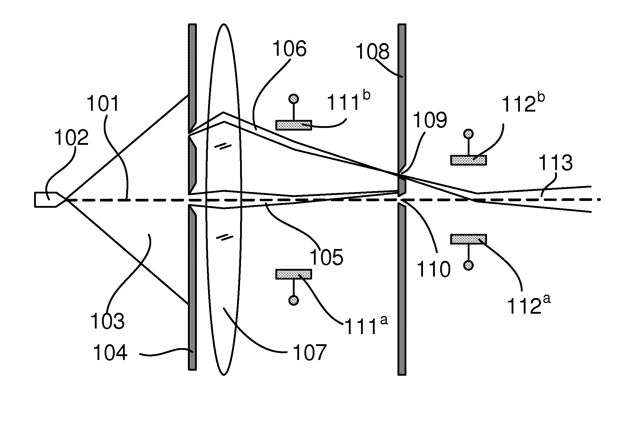
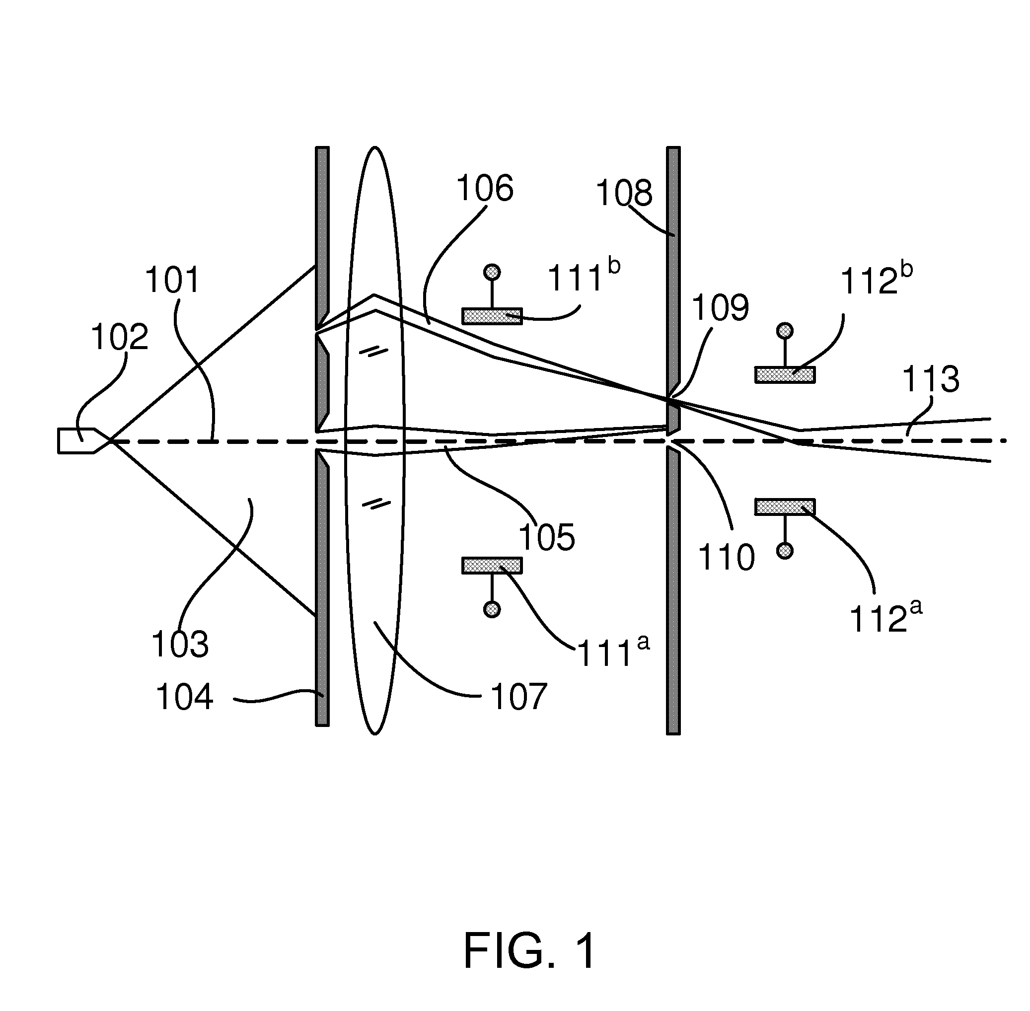
[0021]The invention aims to provide a charged particle source where only one beam leaves the source module.

[0022]To this end the particle source according to the invention is characterised in that when the eccentric beam is focused and aligned on the energy selecting aperture using the second deflector, the second deflector simultaneously deflects the central beam to such an extend that the central beam is blocked by the energy selecting diaphragm.

[0023]When the eccentric beam is aligned on the energy selecting aperture and passes through the energy selecting diaphragm, the central beam is stopped by the energy selecting diaphragm by slightly deflecting the central beam. Preferably the deflection of the central beam is done by the second deflector by the same deflection action that is needed to align the eccentric beam on the energy selecting aperture.

[0024]As a result the central beam does not exit the charged particle source. The particles of the central beam can thus not cause un...


PUM


Abstract

A particle source in which energy selection occurs by sending a beam of electrically charged particles eccentrically through a lens so that energy dispersion will occur in an image formed by the lens. By projecting this image onto a slit in an energy selecting diaphragm, it is possible to allow only particles in a limited portion of the energy spectrum to pass. Consequently, the passed beam will have a reduced energy spread. The energy dispersed spot is imaged on the slit by a deflector. When positioning the energy dispersed spot on the slit, central beam is deflected from the axis to such an extent that it is stopped by the energy selecting diaphragm. Hereby reflections and contamination resulting from this beam in the region after the diaphragm are avoided. Also electron-electron interaction resulting from the electrons from the central beam interacting with the energy filtered beam in the area of deflector is avoided.

Description


Claims


Application Information

Patent Timeline
Owner FEI CO
Why Eureka
Try Eureka