
Magnetic Retrieval Apparatus and Method for Retaining Magnets on a Downhole Magnetic Retrieval Apparatus

a magnetic retrieval and magnetic technology, applied in the direction of manufacturing tools, transportation and packaging, borehole/well accessories, etc., can solve the problem of metal-to-metal scraping

Active Publication Date: 2011-11-24
BAKER HUGHES INC
View PDF7 Cites 15 Cited by
  • Summary
  • Abstract
  • Description
  • Claims
  • Application Information

AI Technical Summary

Problems solved by technology

These shavings and cuttings result from numerous frictional operations that might occur within the wellbore or tubular, including the cutting of sidetracking windows, milling, drilling through stuck devices and objects, as well as general operations that cause metal-to-metal scraping to occur.

Method used


Image

  • Magnetic Retrieval Apparatus and Method for Retaining Magnets on a Downhole Magnetic Retrieval Apparatus
  • Magnetic Retrieval Apparatus and Method for Retaining Magnets on a Downhole Magnetic Retrieval Apparatus
  • Magnetic Retrieval Apparatus and Method for Retaining Magnets on a Downhole Magnetic Retrieval Apparatus

Examples


Embodiment Construction

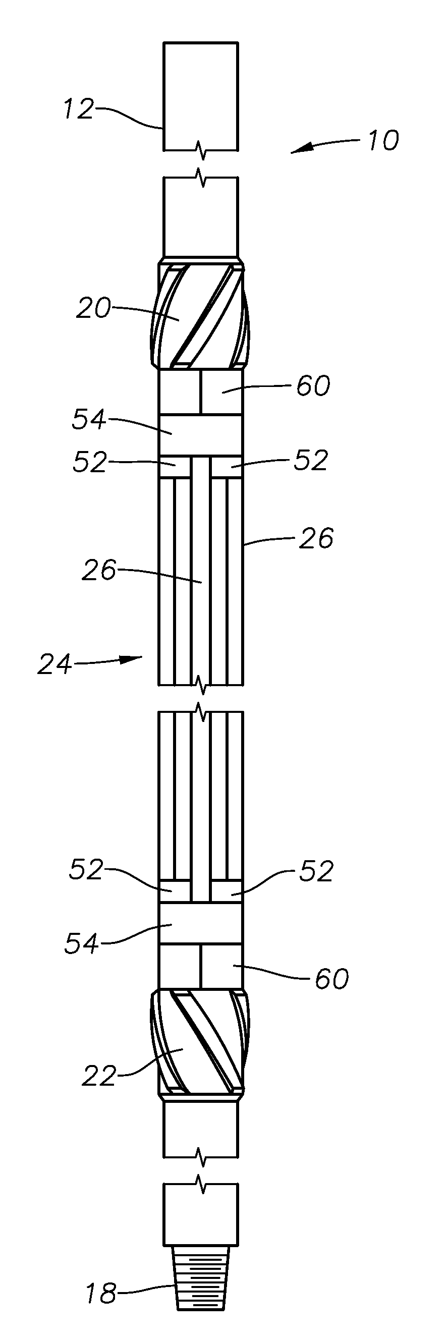
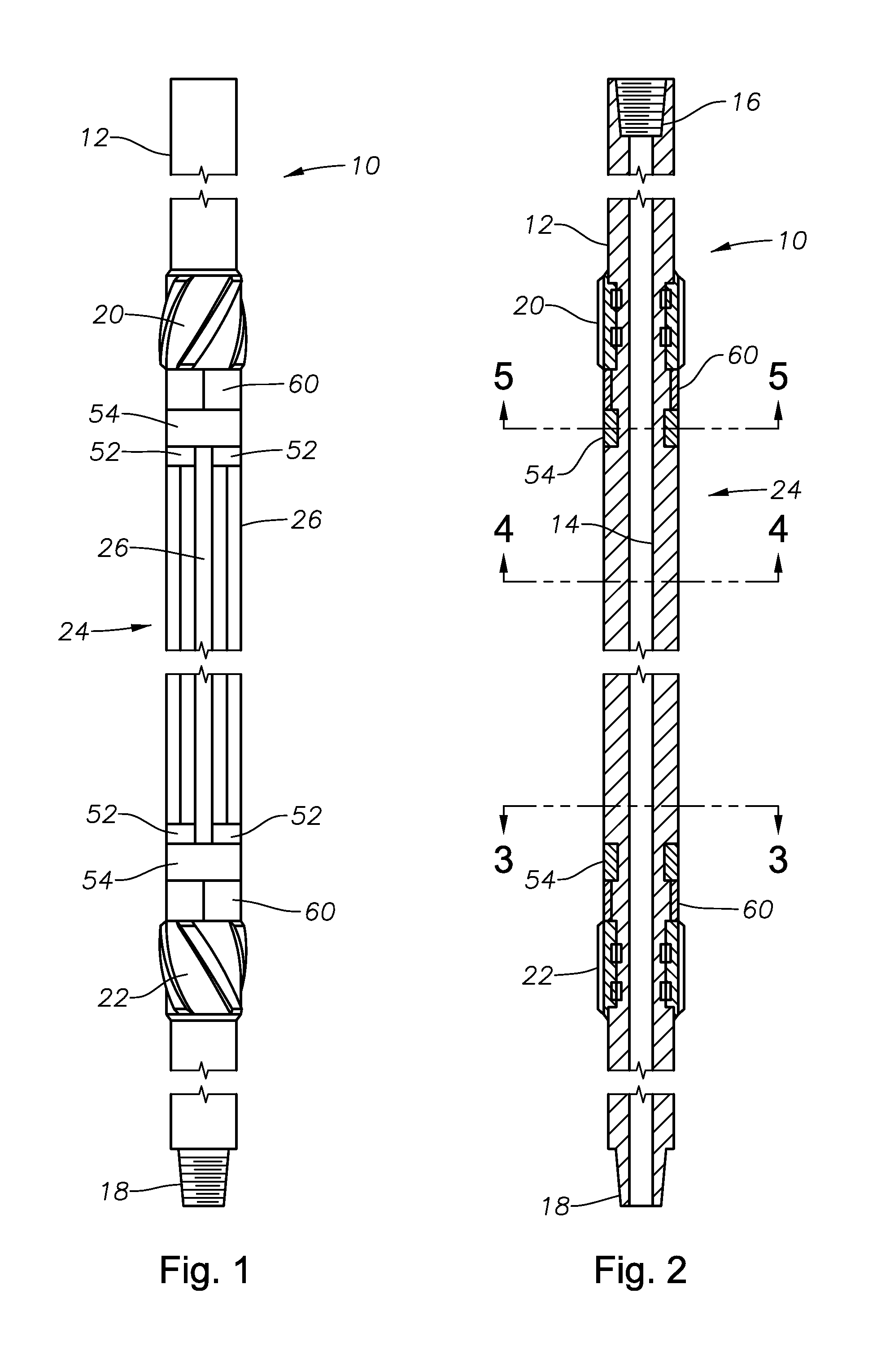
[0021]FIGS. 1-6 illustrate an exemplary magnetic retrieval tool 10 for use in removing metallic debris from a wellbore or other surrounding tubular. The tool 10 includes a generally cylindrical tool body 12 that defines a central axial flowbore 14. The exemplary tool 10 has an upper axial end with a box-type threaded portion 16 and a lower axial end with a pin-type threaded portion 18 for incorporating the tool 10 into a tool string, as is known in the art.

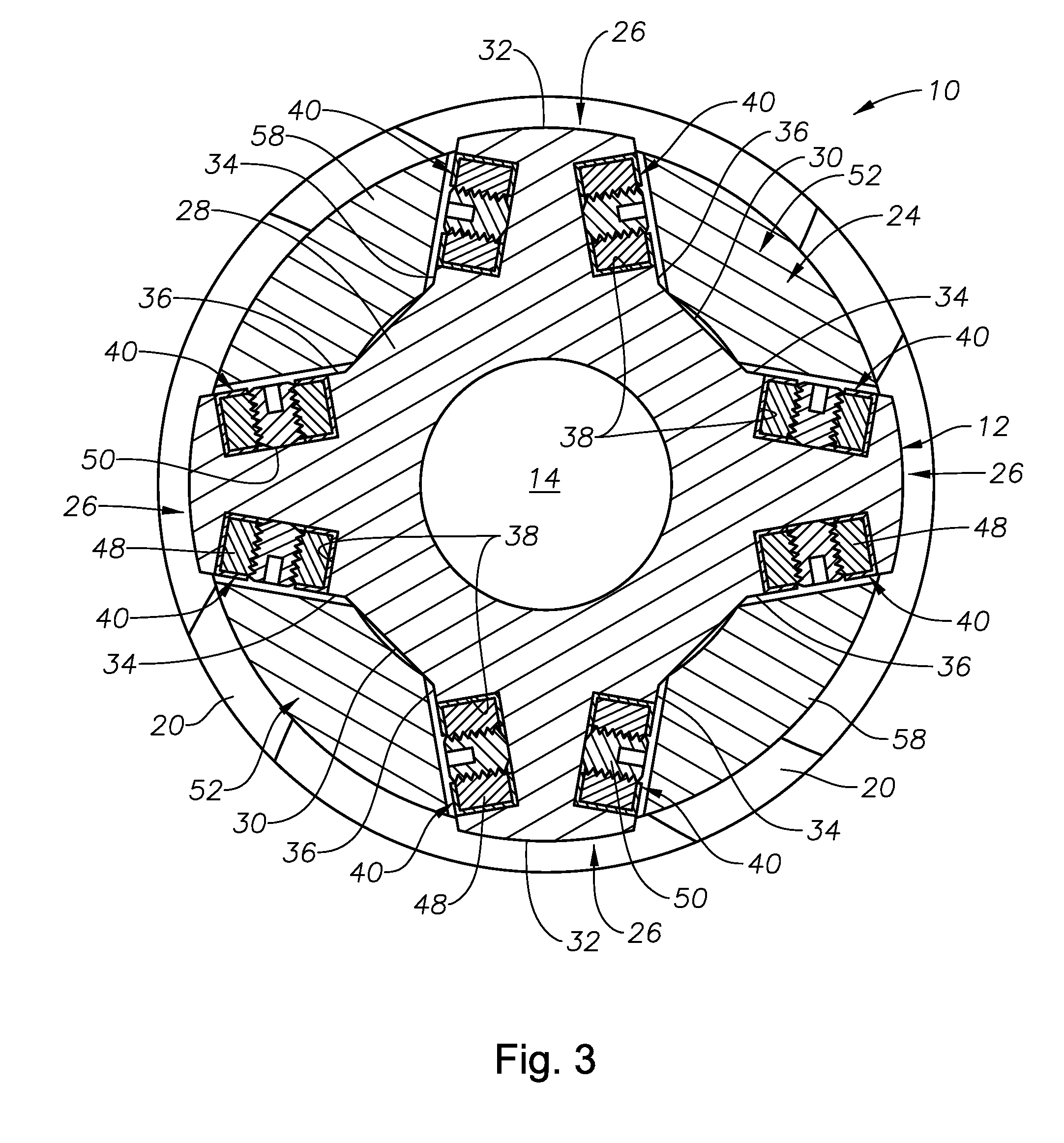
[0022]The tool body 12 carries upper and lower stabilizers 20, 22. The stabilizers 20, 22 are each rotatable with respect to the tool body 12 and may be identical in construction. A magnetic retrieval portion, generally shown at 24, is located axially between the upper and lower stabilizers 20, 22. As best seen in FIGS. 3 and 4, the magnetic retrieval portion 24 includes a plurality of axially extending ribs 26 that project radially outwardly from an inner shaft 28. The shaft 28 presents radially reduced recesses 30 that are locat...


PUM

PropertyMeasurementUnit
Magnetismaaaaaaaaaa

Abstract

Magnetic retrieval tools for use in a wellbore or other tubular member to remove metallic debris. A magnetic retrieval tool includes a tool body having a central shaft with a plurality of ribs that project radially outwardly therefrom. The ribs present lateral sides that have recesses formed therein. Magnet bars are retained within the recesses by wedge members and retaining rings. The magnet bars include a hollow protective housing that encloses a plurality of magnets. Retaining plugs are used to secure the magnets within the housing.

Description

[0001]This application is a continuation-in-part of U.S. patent application Ser. No. 12 / 782,207, which was filed on May 18, 2010.BACKGROUND OF THE INVENTION[0002]1. Field of the Invention[0003]The present invention generally relates to the design of magnetic retrieval devices used for cleaning the interior of tubular members.[0004]2. Description of the Related Art[0005]Metallic debris accumulates within wellbores and other tubular members during production of subterranean fluids, such as hydrocarbon fluids. This metallic debris typically includes tiny metal shavings and cuttings. These shavings and cuttings result from numerous frictional operations that might occur within the wellbore or tubular, including the cutting of sidetracking windows, milling, drilling through stuck devices and objects, as well as general operations that cause metal-to-metal scraping to occur.[0006]Devices used for the removal of metallic debris by magnets are described, for example, in U.S. Pat. No. 7,515,...

Claims


Application Information

Patent Timeline
IPC IPC(8): E21B31/06B23P11/00B66C1/04
CPCE21B17/1078E21B31/06Y10T29/49826E21B37/00
Inventor NELSON, JONATHAN F.HERN, GREGORY L.
Owner BAKER HUGHES INC
Learn More