
System and methods for broad area visual obscuration

a broad area and visual obscuration technology, applied in the field of visual obscuration reduction, can solve the problems of narrow beams, inability to accurately discern the position of aircraft, and small arms that are generally only accurate at close range, so as to achieve the effect of reducing visual obscuration

Inactive Publication Date: 2011-11-24
THE BOEING CO
View PDF0 Cites 0 Cited by
  • Summary
  • Abstract
  • Description
  • Claims
  • Application Information

AI Technical Summary

Benefits of technology

The embodiments of the present system and methods for broad area visual obscuration have several features, no single one of which is solely responsible for their desirable attributes. Without limiting the scope of the present embodiments as expressed by the claims that follow, their more prominent features will now be discussed briefly. After considering this discussion, and particularly after reading the section entitled “Detailed Description”, one will understand how the features of the present embodiments provide advantages, which include the ability to temporarily reduce the visual acuity of any observer located within a broad area, such as an area within which small arms could effectively be used to target a platform but for the visual obscuration provided by the present system and methods.
One aspect of the present system and methods includes the realization that current laser-based visual interrupters are inadequate to cover large areas. They emit narrow beams that cannot prevent observation over an area large enough to prevent use of hand-held weapons against aircraft. Accordingly, a system and methods for obscuring vision over a large area would be of great benefit in protecting aircraft and other platforms.
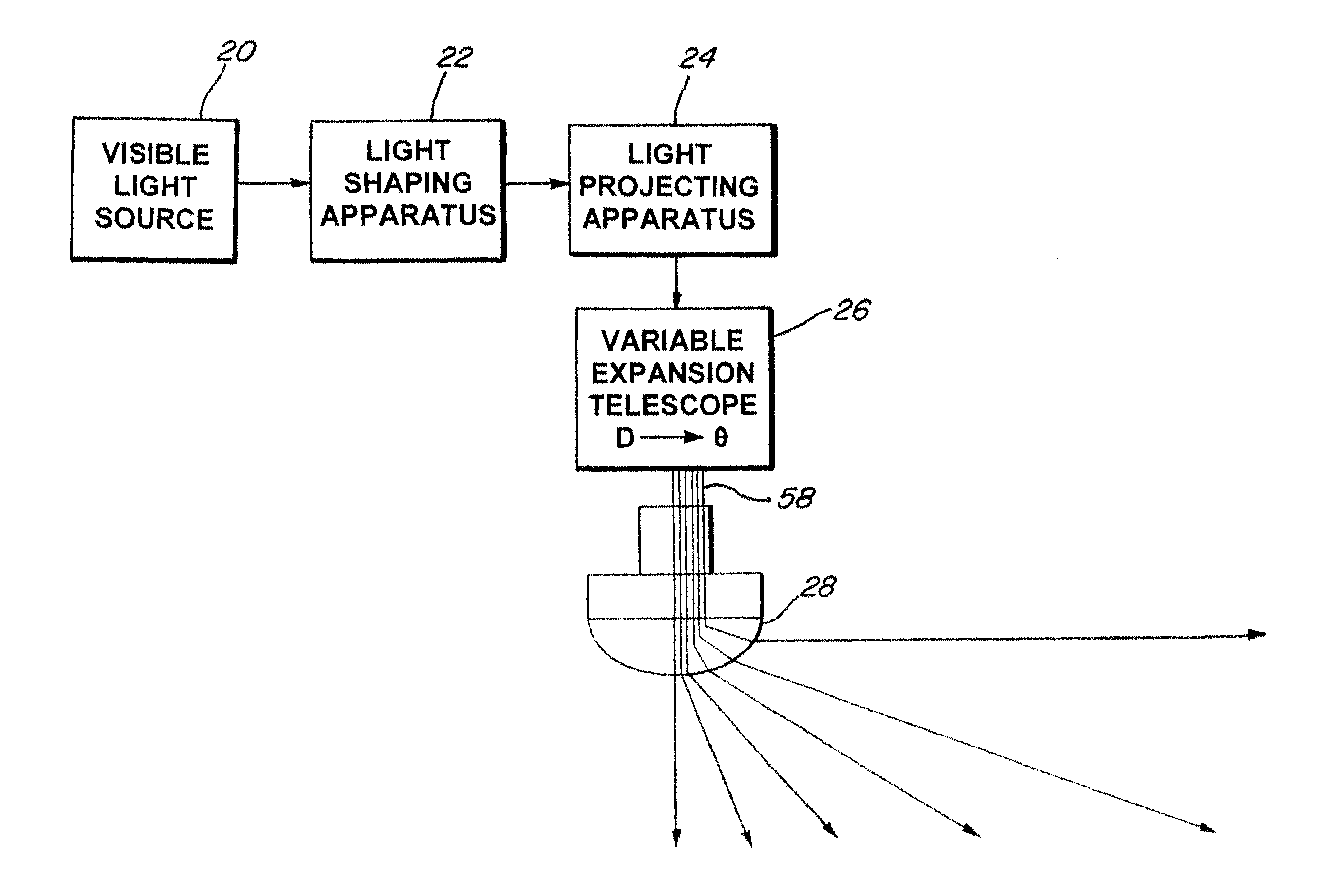
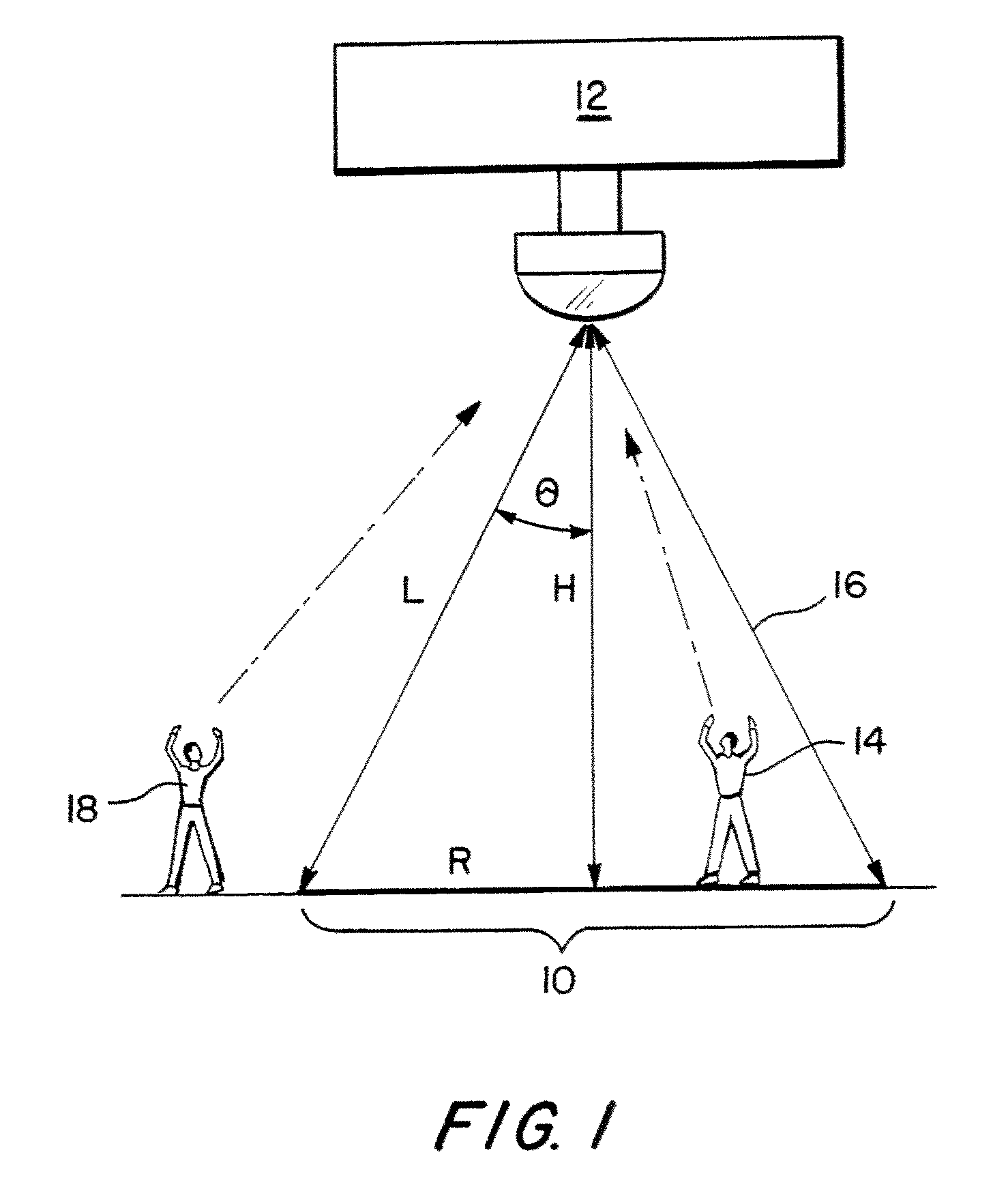
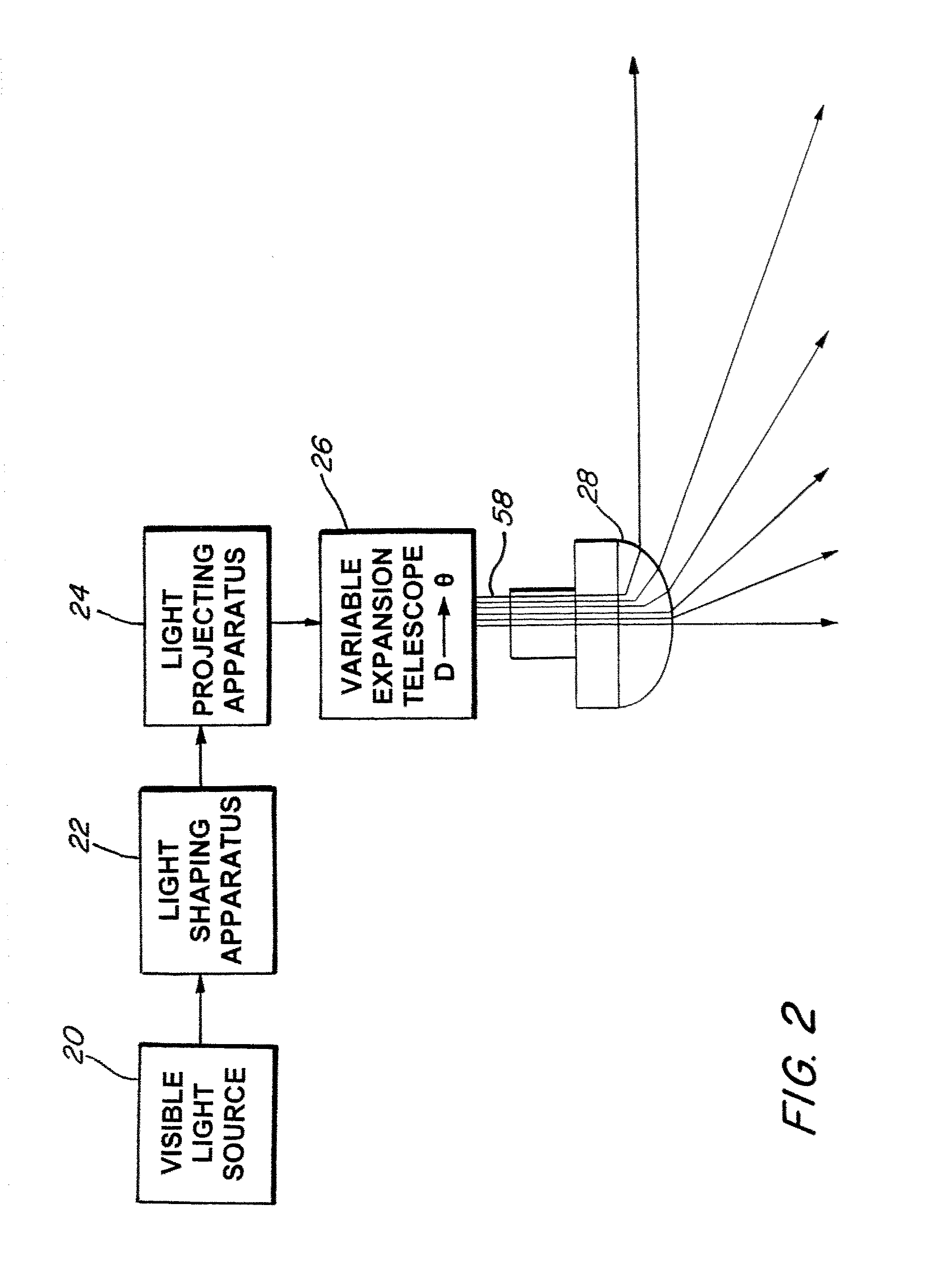
One embodiment of the present system and methods for broad area visual obscuration comprises a source of visible light. Shaping optics are configured to shape the light into a beam having a desired shape. Projecting optics are configured to project the light beam onto an illumination area in a sweeping pattern to repetitively illuminate all portions of the illumination area. A stationary observer within the illumination area receives repeating pulses of the light at a wavelength, power, intensity, frequency and duration sufficient to visually impair the observer so as to substantially prevent the observer from discerning the platform between pulses. The light pulses are capable of temporarily reducing the visual acuity of human eyes but incapable of causing permanent vision loss or impairment.
Another embodiment of the present system and methods for broad area visual obscuration comprises producing visible light, shaping the light into a beam having a desired shape, and projecting the light beam onto the illumination area in a sweeping pattern to repetitively illuminate all portions of the illumination area. A stationary observer within the illumination area receives repeating pulses of the light at a wavelength, power, intensity, frequency and duration sufficient to visually impair the observer so as to substantially prevent the observer from discerning the platform between pulses. The light pulses are capable of temporarily reducing the visual acuity of human eyes but incapable of causing permanent vision loss or impairment.

Problems solved by technology

Further, small arms are generally only accurate at close ranges, such as up to about one kilometer.
Laser-based visual interrupters have been developed to temporarily blind individuals on the ground so that they cannot accurately discern the position of aircraft.
These laser-based systems, however, emit narrow beams that are generally directed at individuals without the benefit of a stabilized pointing system.

Method used


Image

  • System and methods for broad area visual obscuration
  • System and methods for broad area visual obscuration
  • System and methods for broad area visual obscuration

Examples


Embodiment Construction

”, one will understand how the features of the present embodiments provide advantages, which include the ability to temporarily reduce the visual acuity of any observer located within a broad area, such as an area within which small arms could effectively be used to target a platform but for the visual obscuration provided by the present system and methods.

One aspect of the present system and methods includes the realization that current laser-based visual interrupters are inadequate to cover large areas. They emit narrow beams that cannot prevent observation over an area large enough to prevent use of hand-held weapons against aircraft. Accordingly, a system and methods for obscuring vision over a large area would be of great benefit in protecting aircraft and other platforms.

One embodiment of the present system and methods for broad area visual obscuration comprises a source of visible light. Shaping optics are configured to shape the light into a beam having a desired shape. Proj...


PUM


Abstract

A system and methods for broad area visual obscuration around a platform. In one embodiment the system comprises a source of visible light, shaping optics and projecting optics. The system projects a light beam onto an illumination area in a sweeping pattern to repetitively illuminate all portions of the illumination area, such that a stationary observer within the illumination area receives repeating pulses of the light at a power, intensity, frequency and duration sufficient to visually impair the observer so as to substantially prevent the observer from discerning the platform between pulses. The light pulses are capable of temporarily blinding human eyes but incapable of causing permanent vision loss.

Description

BACKGROUND1. Technical FieldThe present disclosure relates to reduction in visual acuity to prevent, for example, perception and / or targeting of platforms.2. Description of Related ArtAircraft flying low or landing in hostile or uncontrolled territory can be targeted by ground-based small arms fire. These weapons, such as machine guns and hand-held rocket launchers, rely on “point-and-shoot” targeting. The shooter sees the target, aims the weapon by aligning his or her eye with an expected trajectory of the projectile, and fires. Thus, the shooter must be able to see the target in order to aim accurately. Further, small arms are generally only accurate at close ranges, such as up to about one kilometer. Therefore, the shooter must be relatively close to the target in order to have a reasonable chance of hitting it.Laser-based visual interrupters have been developed to temporarily blind individuals on the ground so that they cannot accurately discern the position of aircraft. These l...

Claims


Application Information

Patent Timeline
Patent Type & Authority Applications(United States)
IPC IPC(8): G02B27/48F21V17/02F21V9/00
CPCF41H3/00G02B26/10F41H13/0056
Inventor ULLMAN, ALAN Z.ANSPACH, JOEL E.VOELKER, JEFFREY J.
Owner THE BOEING CO
Learn More