
Updating ray traced acceleration data structures between frames based on changing perspective

a technology of acceleration data and frame, applied in the field of image processing, can solve the problems that the processing process may generally reduce the visual acuity of the rendered image, and achieve the effect of reducing the amount of processing resources used, reducing the visual acuity of the rendered image, and reducing the processing requirements

Inactive Publication Date: 2013-01-08
INT BUSINESS MASCH CORP
View PDF11 Cites 24 Cited by
  • Summary
  • Abstract
  • Description
  • Claims
  • Application Information

AI Technical Summary

Benefits of technology

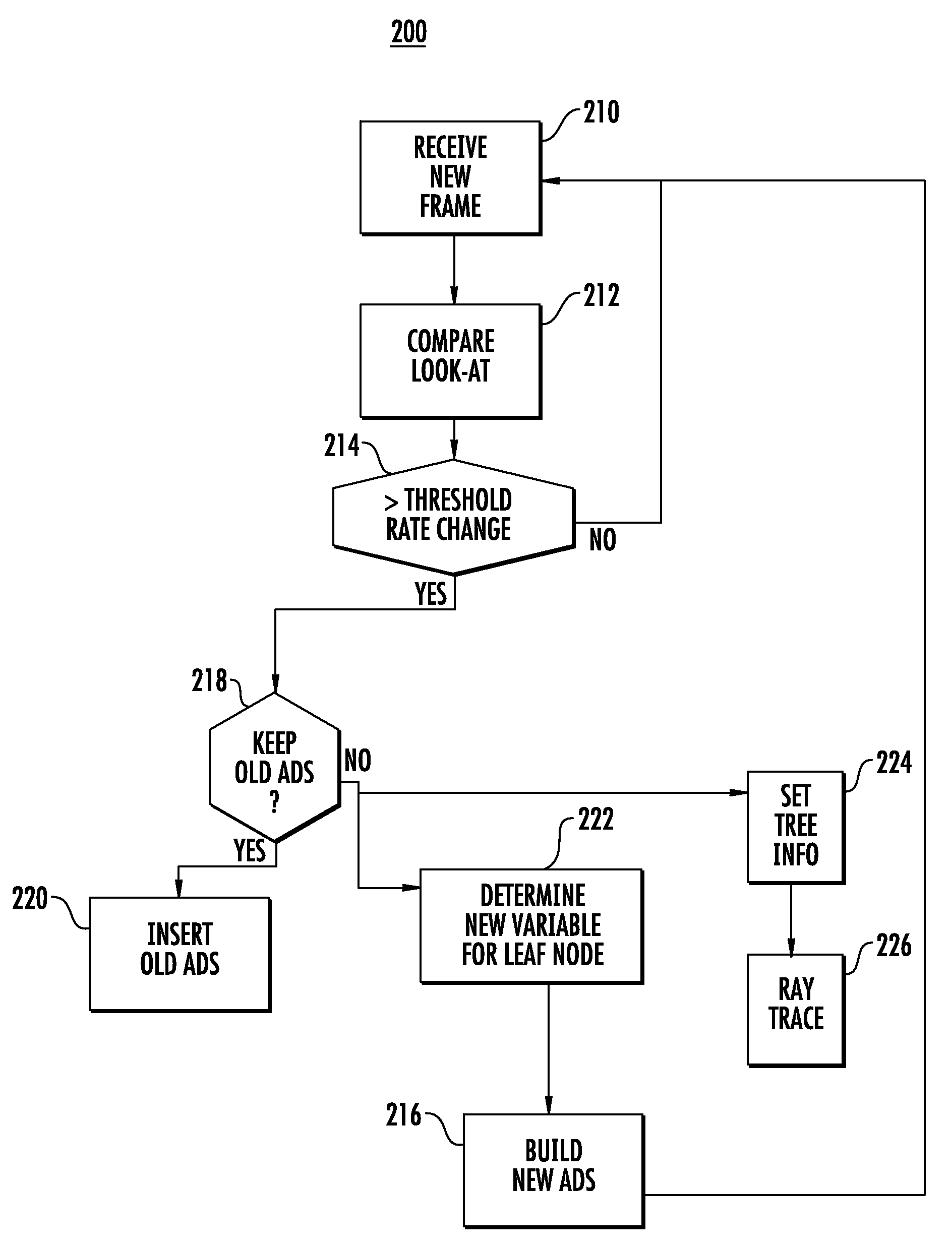
[0011]Aspects of the invention may reduce the amount of processing resources used by reusing an acceleration data structure for a preset number of the plurality of frames. One embodiment may skip building an acceleration data structure for a preset number of the plurality of frames. Processes may generally reduce the visual acuity of the rendered image. Where so configured, the rate of change or other difference between frames may affect the generation of an acceleration data structure associated with one of the plurality of frames.
[0012]Processing requirements may further be reduced by increasing a number of primitives included per node of an acceleration data structure. In the same or another embodiment, the number of generated secondary rays and / or originally cast rays may be reduced. The depth of recursion may similarly be decreased, as may soft shadow quality. The priority assigned to rays may be decreased along with the number of multisampling anti-aliasing samples.
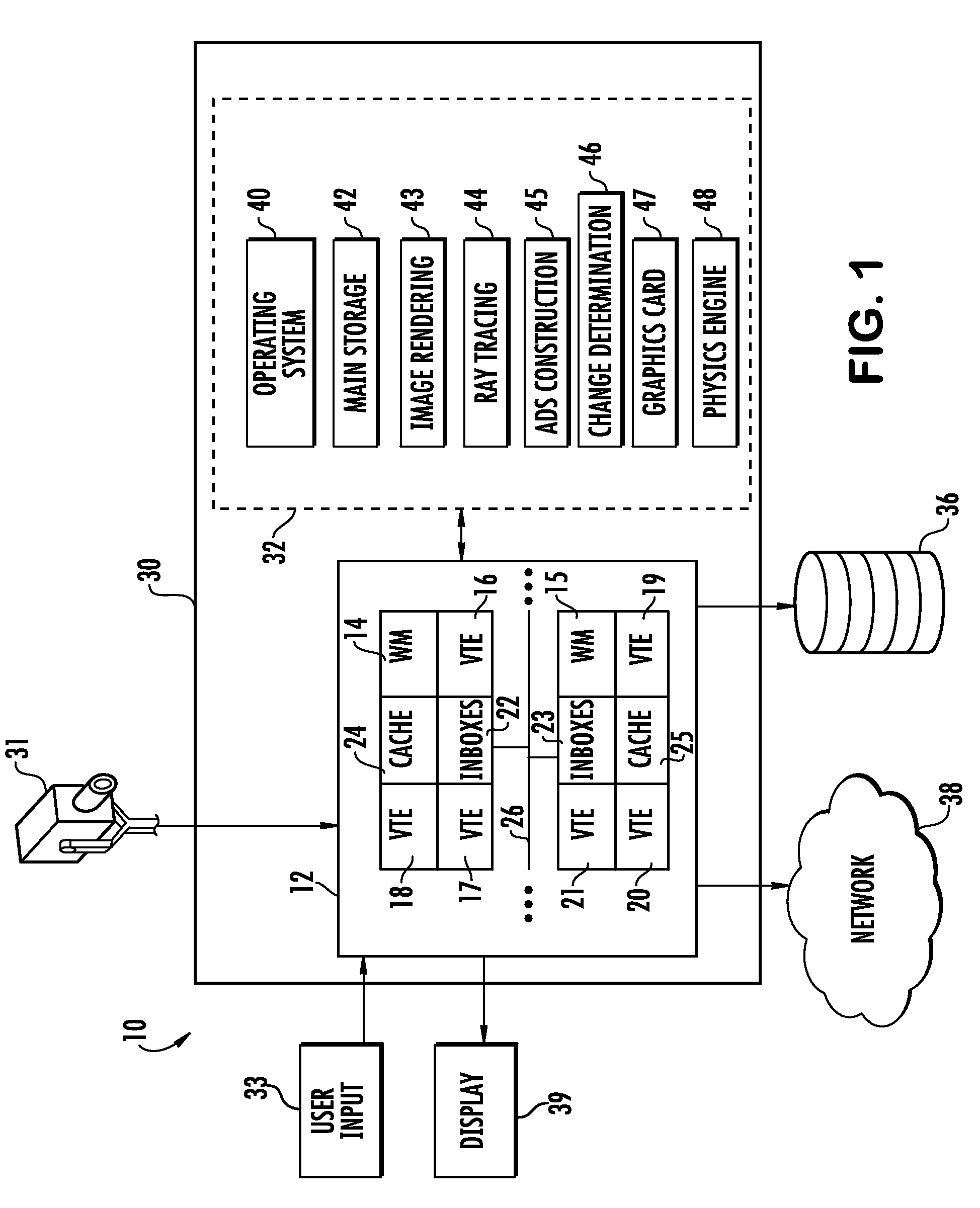
[0016]Aspects of the invention may include a memory configured to store frame information comprising image data, an acceleration data structure including a plurality of nodes that each correspond to a portion of the image data, and program code configured to conduct ray tracing and to determine a difference between respective ray origins of a plurality of frames. The program code may reduce an amount of processing resources used to render an image according to the determined difference. A processor in communication with the memory and configured to execute the program code may reduce the amount of processing resources used to render the image according to the determined difference.

Problems solved by technology

Processes may generally reduce the visual acuity of the rendered image.

Method used


Image

  • Updating ray traced acceleration data structures between frames based on changing perspective
  • Updating ray traced acceleration data structures between frames based on changing perspective
  • Updating ray traced acceleration data structures between frames based on changing perspective

Examples


Embodiment Construction

[0024]Embodiments consistent with the principles of the present invention may provide image rendering in a manner that reduces computational requirements based on the change in perspective between frames. The computational requirement of a ray tracing operation may be reduced in response to a rapid change in the vantage point. Aspects may capitalize on a recognition of a relatively fast rate of change by exchanging visual acuity for saved processing power and other resources.

[0025]Embodiments may include a ray tracing operation where an ADS is updated in between frames in response to a changing vantage point. Aspects of the invention may adjust the quality level of tree building in response to rapid changes in the “look at” of the user. Embodiments may have particular application where graphics-only scene data trees are employed. Alternatively or additionally, ADS building cycles may be skipped. All or some of the ADS may be built in intervals, e.g., after a preset number of frames....


PUM


Abstract

A method, program product and system for conducting a ray tracing operation where the rendering compute requirement is reduced or otherwise adjusted in response to a changing vantage point. Aspects may update or reuse an acceleration data structure between frames in response to the changing vantage point. Tree and image construction quality may be adjusted in response to rapid changes in the camera perspective. Alternatively or additionally, tree building cycles may be skipped. All or some of the tree structure may be built in intervals, e.g., after a preset number of frames. More geometric image data may be added per leaf node in the tree in response to an increase in the rate of change. The quality of the rendering algorithm may additionally be reduced. A ray tracing algorithm may decrease the depth of recursion, and generate fewer cast and secondary rays. The ray tracer may further reduce the quality of soft shadows, resolution and global illumination samples, among other quality parameters. Alternatively, tree rebuilding may be skipped entirely in response to a high camera rate of change. Associated processes may create blur between frames to simulate motion blur.

Description

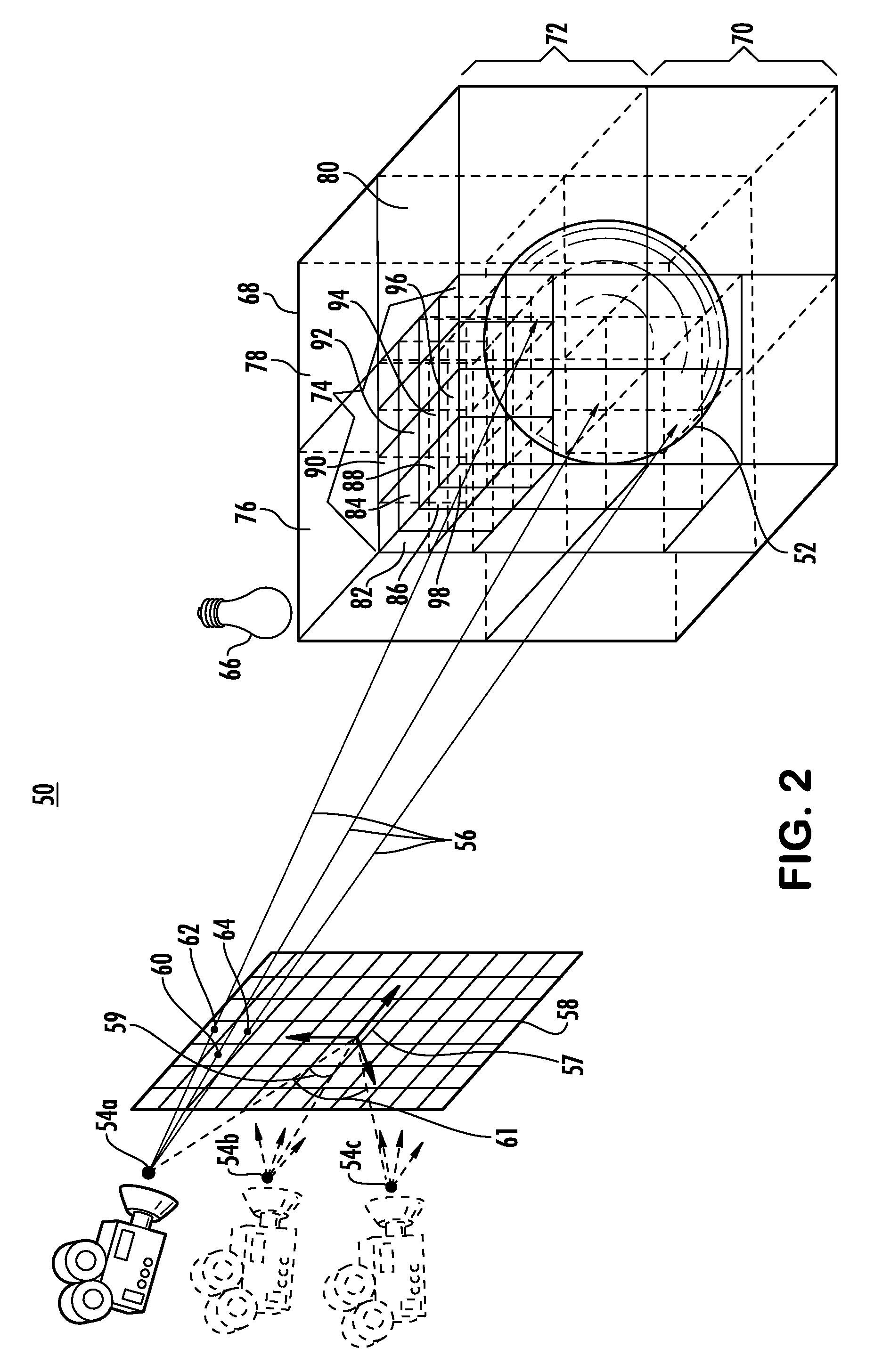
FIELD OF THE INVENTION[0001]The present invention relates generally to image processing, and more particularly, to updating an acceleration data structure (ADS) in response to a vantage point changing between frames of a ray tracing operation.BACKGROUND OF THE INVENTION[0002]Ray tracing has become mainstream in video game animation, motion picture and other media applications. Ray tracing describes a technique for synthesizing photorealistic images by identifying and summing paths connecting light sources with cameras. Rays are traced along the line of sight to determine visibility and from light sources to determine illumination.[0003]A ray comprises a half line of infinite length. A ray originates at a point in space described by a position vector and travels along a direction vector. Ray tracing is used in computer graphics to determine visibility by directing the ray from the origin along a line of sight described by the direction vector. The ray is tested for intersection again...

Claims


Application Information

Patent Timeline
Patent Type & Authority Patents(United States)
IPC IPC(8): G06T15/00G06T15/50G06T15/60G06T1/00G06F17/00
CPCG06T17/005G06T15/06
Inventor MEJDRICH, ERIC OLIVERSCHARDT, PAUL EMERYSHEARER, ROBERT ALLENTUBBS, MATTHEW RAY
Owner INT BUSINESS MASCH CORP
Learn More