Latched connector assembly

a connector and assembly technology, applied in the direction of coupling device connection, coupling parts engagement/disengagement, electrical apparatus, etc., can solve the problems of preventing productivity enhancement and high cost, and achieve the effect of reducing costs, speeding up the fabrication process, and enhancing productivity

Inactive Publication Date: 2011-11-24
KS TERMINALS INC
View PDF1 Cites 8 Cited by
  • Summary
  • Abstract
  • Description
  • Claims
  • Application Information

AI Technical Summary

Benefits of technology

[0007]Hence, it is a primary objective of the present invention to provide such a latched connector assembly. The first and second connecting devices of the latched connector assembly have the first engaging structures for securing the terminal connectors in position to thereby dispense with a pin which might otherwise be required to fasten the terminal connectors in position. Hence, the latched connector assembly of the present invention is effective in cutting costs.
[0008]Another objective of the present invention is to provide such a latched connector assembly. The first and second connecting devices of the latched connector assembly have the first engaging structures for securing the terminal connectors in position to thereby dispense with the step of inserting a pin. Hence, the latched connector assembly of the present invention is effective in speeding up the fabrication process and enhancing productivity.

Problems solved by technology

The aforesaid process has two other drawbacks: the process requires the pin 94 which is made of metal and thus incurs high costs; and the step of inserting the pin 94 and securing the pin 94 in position prevents enhancement of productivity.

Method used


Image

  • Latched connector assembly
  • Latched connector assembly
  • Latched connector assembly

Examples


Embodiment Construction

[0025]The present invention essentially discloses a latched connector assembly. Fundamental principles of latched connection embodied in the present invention are comprehensible by persons skilled in the art and thus are not described in detail hereunder. Also, the drawings corresponding to the description below are schematic, structural illustrations of the features of the present invention, and are not and have not to be drawn to scale.

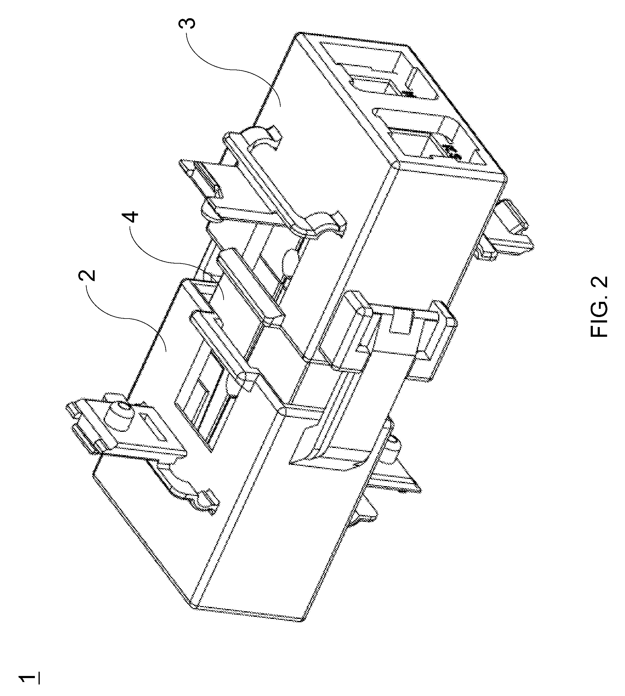
[0026]Referring to FIG. 2, a latched connector assembly 1 of the present invention essentially comprises a first connecting device 2, a second connecting device 3, and terminal connectors 4 latched to the first and second connecting devices 2, 3. Referring to FIG. 3A, the first connecting device 2 comprises a first casing 20 and at least two said terminal connectors 4 received in the first casing 20. Referring to FIG. 3B and FIG. 3C, FIG. 3B is a cross-sectional view taken along line A-A of FIG. 3A, and FIG. 3C is a top view of the first connecting ...


PUM


Abstract

A latched connector assembly includes a first connecting device and a second connecting device latched to each other. The first connecting device has a first casing and two terminal connectors received in the first casing. The first casing has first and second side walls. The first side walls have first engaging structures protruding outward. The second side walls each have an extending arm that has a second engaging structure. The second connecting device has a second casing and at least two terminal connectors received in the second casing. The second casing has third and fourth side walls. The third side walls have first engaging structures protruding outward. The fourth side walls each have a locking portion protruding outward for receiving the second engaging structures of the first connecting device. The terminal connectors are received, in opposite directions, in the first casing and the second casing, respectively.

Description

BACKGROUND OF THE INVENTION[0001]1. Technical Field[0002]The present invention relates to connector assemblies, and more particularly, to a connector assembly having a latched device.[0003]2. Description of Related Art[0004]Connectors are widely applied to various industries and a wide variety of electrical equipment. Users transmit required data, signals, and electricity quickly through the use of connectors. The advent of connectors speeds up information reception and promotes convenience of daily life.[0005]Referring to FIG. 1, regarding a first connecting device 91, a second connecting device 92, and a terminal connector 93 disclosed according to the prior art, with a pin 94, the terminal connector 93 is fixed to the prior-art first connecting device 91 or to the prior-art second connecting device 92. However, the process of fixing the terminal connector 93 to the prior-art first connecting device 91 or to the prior-art second connecting device 92 by the pin 94 entails the step ...

Claims


Application Information

Patent Timeline
IPC IPC(8): H01R13/62
CPCH01R13/514H01R13/639H01R13/6273H01R13/518Y10S439/903
Inventor LIN, CHIH-HSIN
Owner KS TERMINALS INC
Why Eureka
Try Eureka