Wireless Communication System and Communication Control Method

a communication system and control method technology, applied in the field of wireless communication systems, can solve the problem of not having a specific communication procedure for selecting antennas across a plurality of cells, and achieve the effects of reducing inter-cell interference, improving frequency usage efficiency, and improving communication quality of terminals

Inactive Publication Date: 2011-11-24
HITACHI LTD
View PDF6 Cites 78 Cited by
  • Summary
  • Abstract
  • Description
  • Claims
  • Application Information

AI Technical Summary

Benefits of technology

[0017]According to the embodiment of this invention, it is possible to reduce the inter-cell interference. Accordingly, it is possible to improve the communication quality of the terminal in the vicinity of the cell boundary. In other words, it is possible to improve frequency usage efficiency at the cell boundary and to reduce the gap of quality between services provided terminals.

Problems solved by technology

However, there has been proposed no specific communication procedure for selecting antennas across a plurality of cells in order to realize the network MIMO.

Method used


Image

  • Wireless Communication System and Communication Control Method
  • Wireless Communication System and Communication Control Method
  • Wireless Communication System and Communication Control Method

Examples


first embodiment

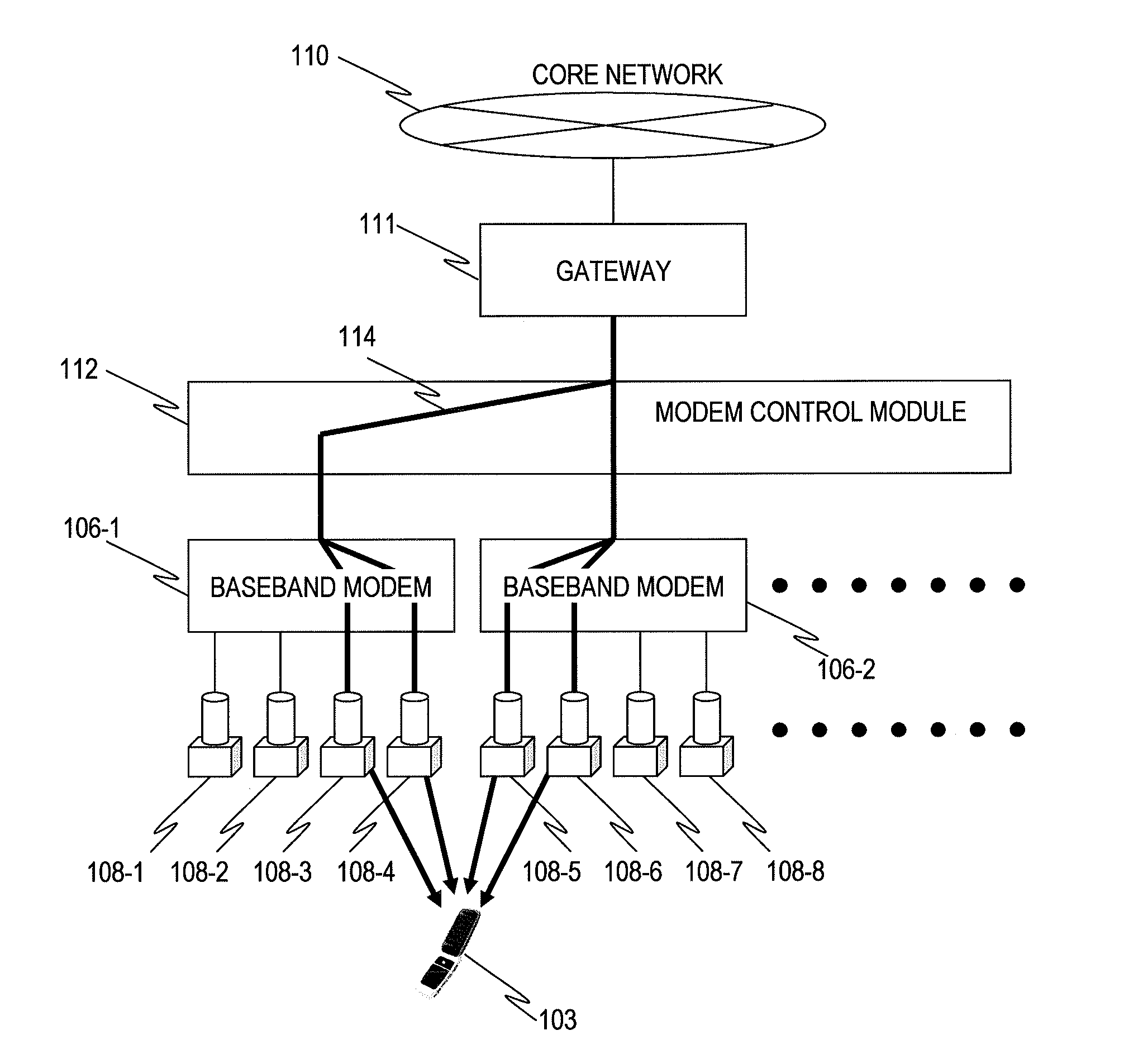
[0058]FIG. 1 is a diagram illustrating a network configuration of a wireless communication system according to a first embodiment.

[0059]The wireless communication system according to the first embodiment includes a gateway 111, modem control module 112, baseband modems 106-1, 106-2, . . . (hereinafter, referred to simply as “106” if distinction between the baseband modems is not necessary), and remote radio units (RRUs) 108-1, 108-2, . . . (hereinafter, referred to simply as “108” if distinction between the RRUs is not necessary). The wireless communication system according to this embodiment is provided with a plurality of baseband modems 106, but may be provided with one baseband modem 106. Further, the wireless communication system according to this embodiment is provided with a plurality of RRUs 108, but in the case of being provided with the plurality of baseband modems 106, may be provided with one RRU 108 for each of the baseband modems 106.

[0060]The gateway 111 is a node for...

second embodiment

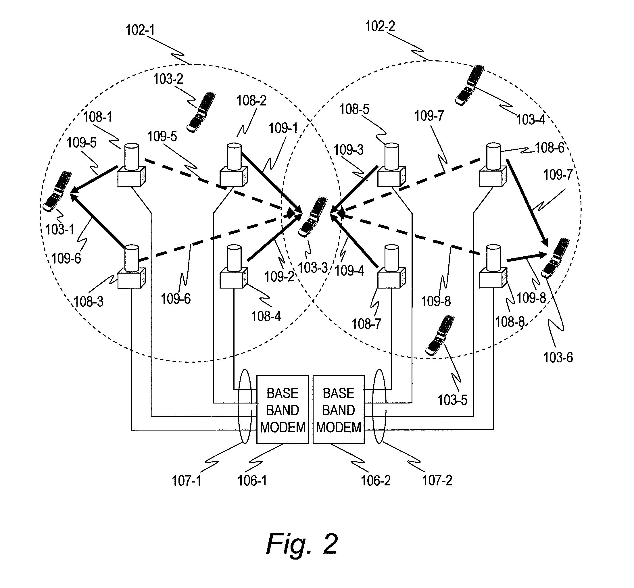
[0200]FIG. 22 is a diagram illustrating a network configuration of a wireless communication system according to a second embodiment of this invention.

[0201]The wireless communication system according to the second embodiment is different from the wireless communication system according to the first embodiment in which the baseband modems 106 and the RRUs 108 are coupled to each other based on a predetermined correspondence relationship in that the modem-RRU switch 113 is provided between the baseband modems 106 and the RRUs 108. It should be noted that, with regard to the second embodiment, only points thereof different from the above-mentioned first embodiment are described, and descriptions of the same configurations and the same processings as those of the above-mentioned first embodiment are omitted.

[0202]The modem-RRU switch 113 changes over a switch according to an instruction from the modem control module 112, and changes over a coupling between at least one antenna port of t...


PUM


Abstract

It is provided a wireless communication system comprising base stations that communicate with a terminal. Each of the base station has antennas. Each of the base stations transmits a first reference signal unique to each of the antennas which does not overlap with another antenna among the base stations at least in a vicinity thereof. The terminal receives the first reference signal and estimates a received power of the first reference signal for each of the antennas, selects antennas suitable for communication from among the antennas based on a result of estimating the received power, and transmits a result of selecting the antennas to the each of the base stations. The each of the base stations refers the result of selecting the antennas transmitted from the terminal, assigns the selected antennas belonging to different cells to the terminal, and notifies the terminal of a result of assigning the antennas.

Description

BACKGROUND OF THE INVENTION[0001]This invention relates to a wireless communication system, in particular, a wireless communication system in which a terminal communicates with a plurality of base stations.[0002]FIG. 31 is a diagram illustrating a conventional cellular system.[0003]Two base stations 101-1 and 101-2 form cells 102-1 and 102-2, respectively. Three terminals 103-1, 103-2, and 103-3 within the cell 102-1 communicate with the base station 101-1, and three terminals 103-4, 103-5, and 103-6 within the cell 102-2 communicates with the base station 101-2.[0004]Each of the base stations and each of the terminals include a plurality of antennas. Each of the base stations performs multiple input multiple output (MIMO) communication with one terminal belonging to a cell formed by the base station at a given instant. It should be noted that in a multicarrier communication system such as an orthogonal frequency division multiple access (OFDMA), it is possible to perform the MIMO c...

Claims


Application Information

Patent Timeline
Patent Type & Authority Applications(United States)
IPC IPC(8): H04W4/00
CPCH04B7/061H04B7/024
Inventor FUJISHIMA, KENZABUROONO, GOTAKADA, MAYUWANO, KOKI
Owner HITACHI LTD
Why Eureka
Try Eureka