Flush Unit For a Fountain Dispenser

a fountain dispenser and flushing unit technology, applied in the direction of liquid handling, cleaning using liquids, instruments, etc., can solve the problems of heavy conventional devices, unsatisfactory overfilling of drain reservoirs, fluid spillage, etc., and achieve the effect of quick and safe connection

Inactive Publication Date: 2011-12-01
CAMPBELL STEVEN WAYNE +1
View PDF10 Cites 4 Cited by
  • Summary
  • Abstract
  • Description
  • Claims
  • Application Information

AI Technical Summary

Benefits of technology

[0003]In one embodiment, the present invention is a flush unit that can quickly and safely connect to a conventional soda fountain dispenser for cleaning the drain system of the dispenser. The flush unit comprises a one-piece unitary flush block or housing, a flexible hose, and a nozzle. The flush block comprises a fluid conduit having a water inlet port and a water outlet port. The flush block further comprises a plug port for plugging the syrup outlet port of a conventional back block. The water inlet and plug ports are spaced to engage with the water and syrup outlet ports, respectively, of the back block. The flush block further comprises a fastener adapted to engage with a fastener of the back block. The flexible hose has a first end connected by a fastener to the water outlet port of the flush block and a second end connected to the nozzle. The present invention allows a person to quickly connect the flush unit to a conventional dispenser and flush the drain system of the dispenser using its own hydrostatic water source. The present invention eliminates the need for carrying independent pressurized Co2 / air flushing tanks.

Problems solved by technology

Over time, drain hoses of fountain dispenser become clogged leading to an undesired overfill of the drain reservoir and spillage of fluid.
Although providing adequate cleaning with high pressure, such conventional devices are heavy and require transportation of the tank to and from the location of the fountain dispenser.

Method used


Image

  • Flush Unit For a Fountain Dispenser
  • Flush Unit For a Fountain Dispenser
  • Flush Unit For a Fountain Dispenser

Examples


second embodiment

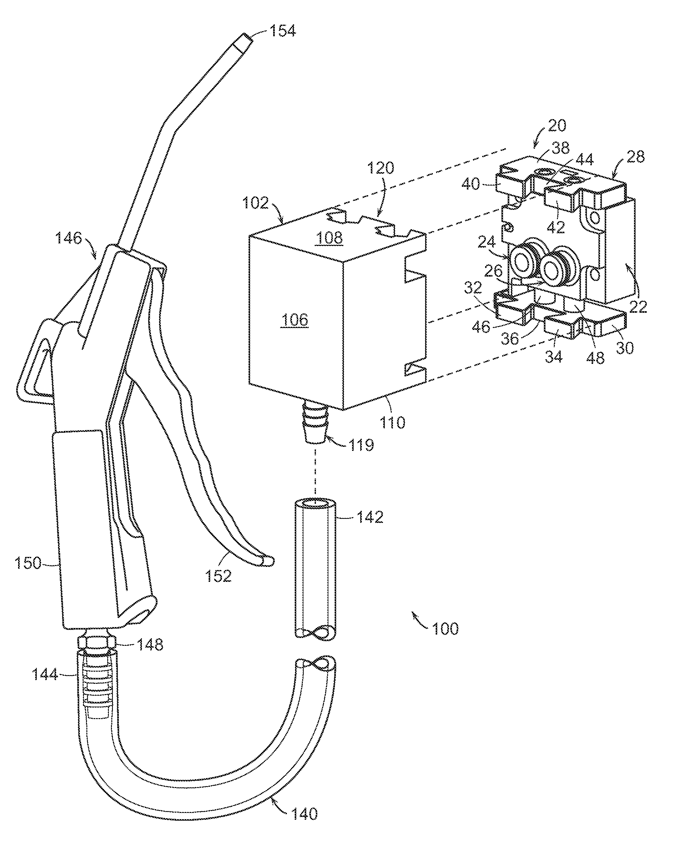
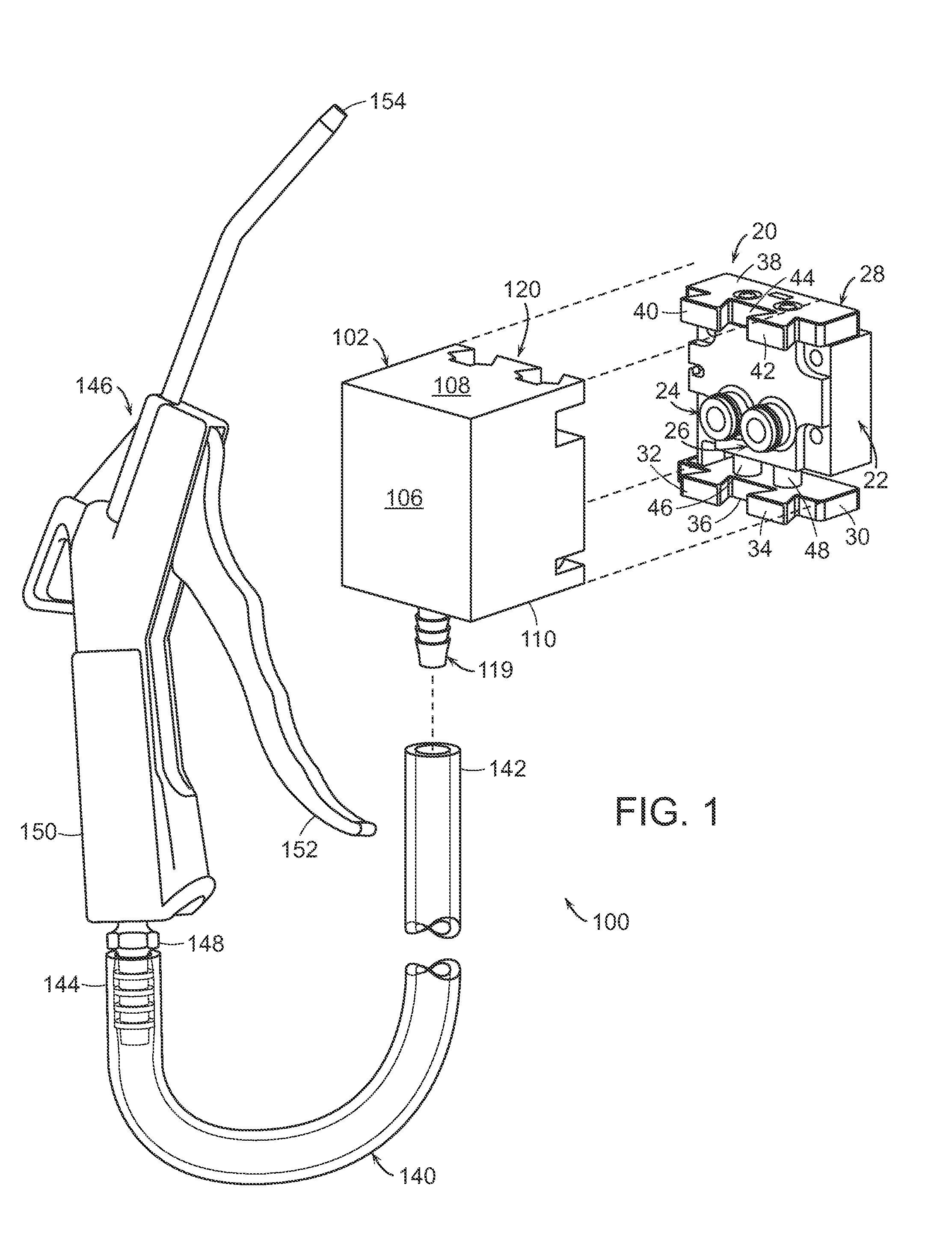
[0026]Referring to FIGS. 6-9, where a flush unit 200 according to the present invention is shown for use with a back block 50 of a second type of soda fountain dispenser (not shown).

[0027]Similar to back block 20, back block 50 has a housing 52 and water and syrup outlet ports 54 and 56. Back block 50 has a fastener 58 that removably engages and / or receives a fastener 220 (to be described) of a flush block 202 (to be described). In the embodiment shown, fastener 58 comprises left and right flanges or bosses 64 and 66 positioned adjacent water outlet port 54 and syrup outlet port 56, respectively. Fastener 58 further comprises holes 56 and 58 passing thru left and right flanges 60 and 64, respectively.

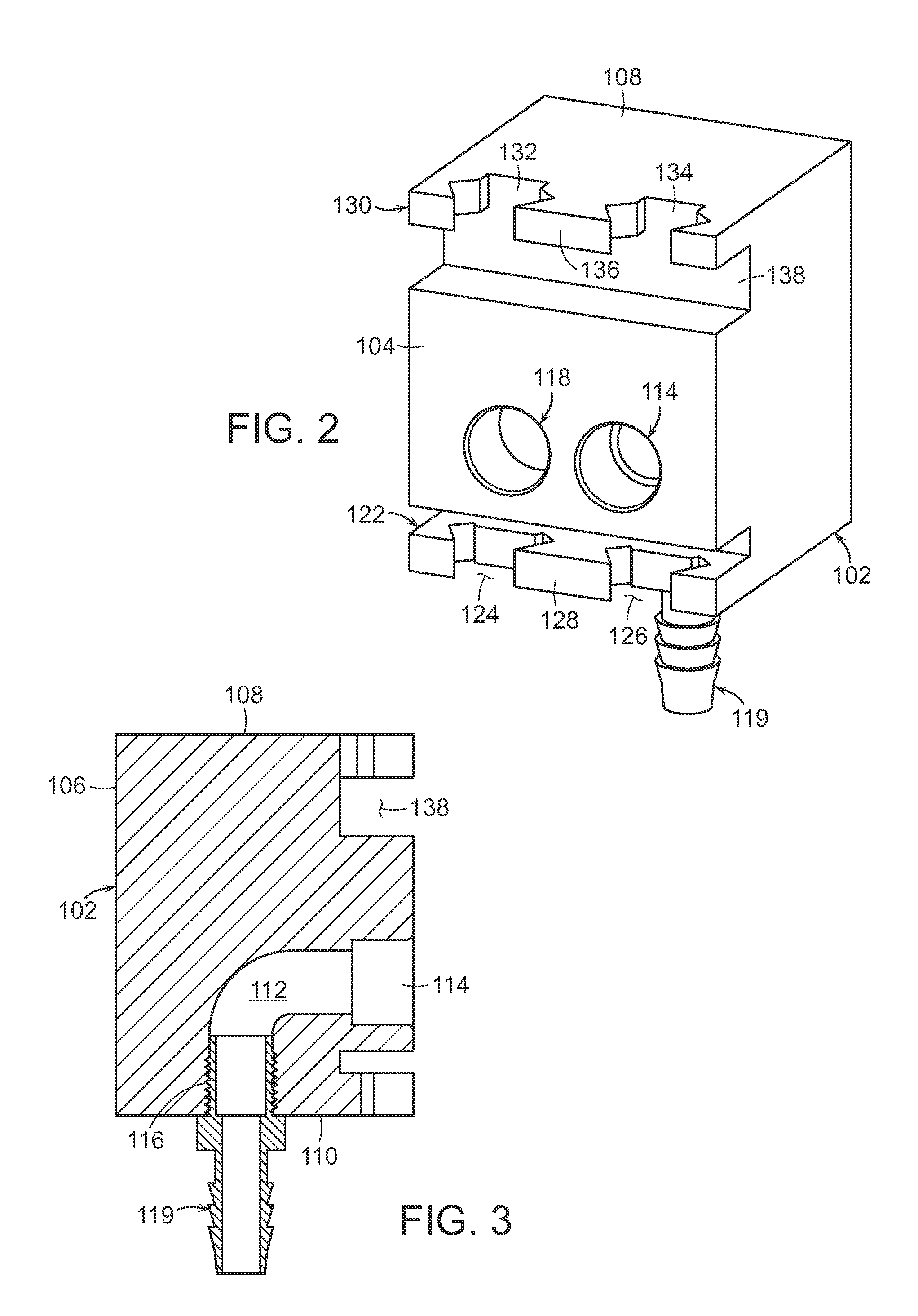
[0028]Flush unit 200 generally comprises a one-piece unitary flush block or housing 202, a flexible hose 140 (previously described), and a nozzle 146 (previously described). Flush block 202 comprises a front face 204, a rear face 206, a top face 208, and a bottom face 210. Front face 20...

third embodiment

[0030]Referring to FIGS. 10-13, where a flush unit 300 according to the present invention is shown for use with a back block 68 of a third type of conventional fountain dispenser (not shown). Similar to back blocks 20 and 50, back block 68 comprises a housing 70 having water and syrup outlet ports 72 and 74. Back block 68 further comprises a fastener 76 that removably engages and / or receives a fastener 320 (to be described) of flush block 300. In the embodiment shown, fastener 76 comprises left and right flanges or bosses 78 and 82 positioned above water outlet port 72 and syrup outlet port 74, respectively. Fastener 76 further comprises holes 80 and 84 passing thru left and right flanges 78 and 82, respectively. Fastener 76 further comprises lower and upper guides 86 and 88. Fastener 76 further comprises a lower flange 90 having a hole 92.

[0031]Flush unit 200 generally comprises a one-piece unitary flush block or housing 302, a flexible hose 140 (previously described), and a nozzle...


PUM


Abstract

The present invention is a flush unit that can quickly and safely connect to a conventional soda fountain dispenser for cleaning the drain system of the dispenser. The flush unit comprises a one-piece unitary flush block or housing, a flexible hose, and a nozzle. The flush block comprises a fluid conduit having a water inlet port and a water outlet port. The flush block further comprises a plug port for plugging the syrup outlet port of a conventional back block. The water inlet and plug ports are spaced to engage with the water and syrup outlet ports, respectively, of the back block. The flush block further comprises a fastener adapted to engage with a fastener of the back block. The flexible hose has a first end connected by a fastener to the water outlet port of the flush block and a second end connected to the nozzle. The present invention allows a person to quickly connect the flush unit to a conventional dispenser and flush the drain system of the dispenser using its own hydrostatic water source. The present invention eliminates the need for carrying independent pressurized Co2/air flushing tanks.

Description

CROSS-REFERENCE TO RELATED APPLICATIONS[0001]This application claims priority to U.S. Provisional Application Ser. No. 61 / 348,199 filed on May 25, 2010, now pending, which is hereby incorporated by reference into this specification in its entirety.BACKGROUND OF THE INVENTION[0002]The present invention relates to devices, systems, and methods for cleaning commercial soda fountains and other dispensing machines. Over time, drain hoses of fountain dispenser become clogged leading to an undesired overfill of the drain reservoir and spillage of fluid. Conventional cleaning devices consist of a hose connected to a tank of carbon dioxide (Co2). Although providing adequate cleaning with high pressure, such conventional devices are heavy and require transportation of the tank to and from the location of the fountain dispenser. Transporting and handling of heavy tanks presents significant safety concerns especially with Co2 inside service vehicles.SUMMARY OF THE INVENTION[0003]In one embodime...

Claims


Application Information

Patent Timeline
Patent Type & Authority Applications(United States)
IPC IPC(8): B08B9/027F16K51/00
CPCB67D1/07B08B9/0321Y10T137/0424Y10T137/5283Y10T137/4238
Inventor CAMPBELL, STEVEN WAYNESMITH, JR., CHARLES ERNEST
Owner CAMPBELL STEVEN WAYNE
Why Eureka
Try Eureka