Electromagnetic valve

Active Publication Date: 2011-12-01
SCHAEFFLER TECH AG & CO KG
View PDF3 Cites 0 Cited by
  • Summary
  • Abstract
  • Description
  • Claims
  • Application Information

AI Technical Summary

Benefits of technology

[0008]The considerably reduced risk of material fatigue of the sealing ring in the case of this design of the sealing ring to valve guide contact can be minimized yet further, in addition, in that the inner circumferential surface of the sealing ring surrounds the valve closure member with a clearance fit. This clearance fit is to be dimensioned, on the one hand, so as to be so small that the hydraulic pressure equalization at the valve closure member is not inadmissibly impaired and, on the other hand, so as to be so great that the radial clearance between the valve closure member and the sealing ring absorbs, at least to a large extent, a tilt component of the valve closure member aligning angularly on the valve seat.
[0009]Moreover, material chips on the sealing ring surface can be prev

Problems solved by technology

However, practical trials by the applicant have shown that, in the ease of the known designs in respect of the sealing ring to valve guide contact, premature material fatigue of the PTFE sealing ring can occur.
The fatigue results in chips on the surface of the material of the sealing ring, which significantly impair its required sealing effect and,

Method used


Image

  • Electromagnetic valve
  • Electromagnetic valve
  • Electromagnetic valve

Examples


Example

DETAILED DESCRIPTION OF THE DRAWINGS

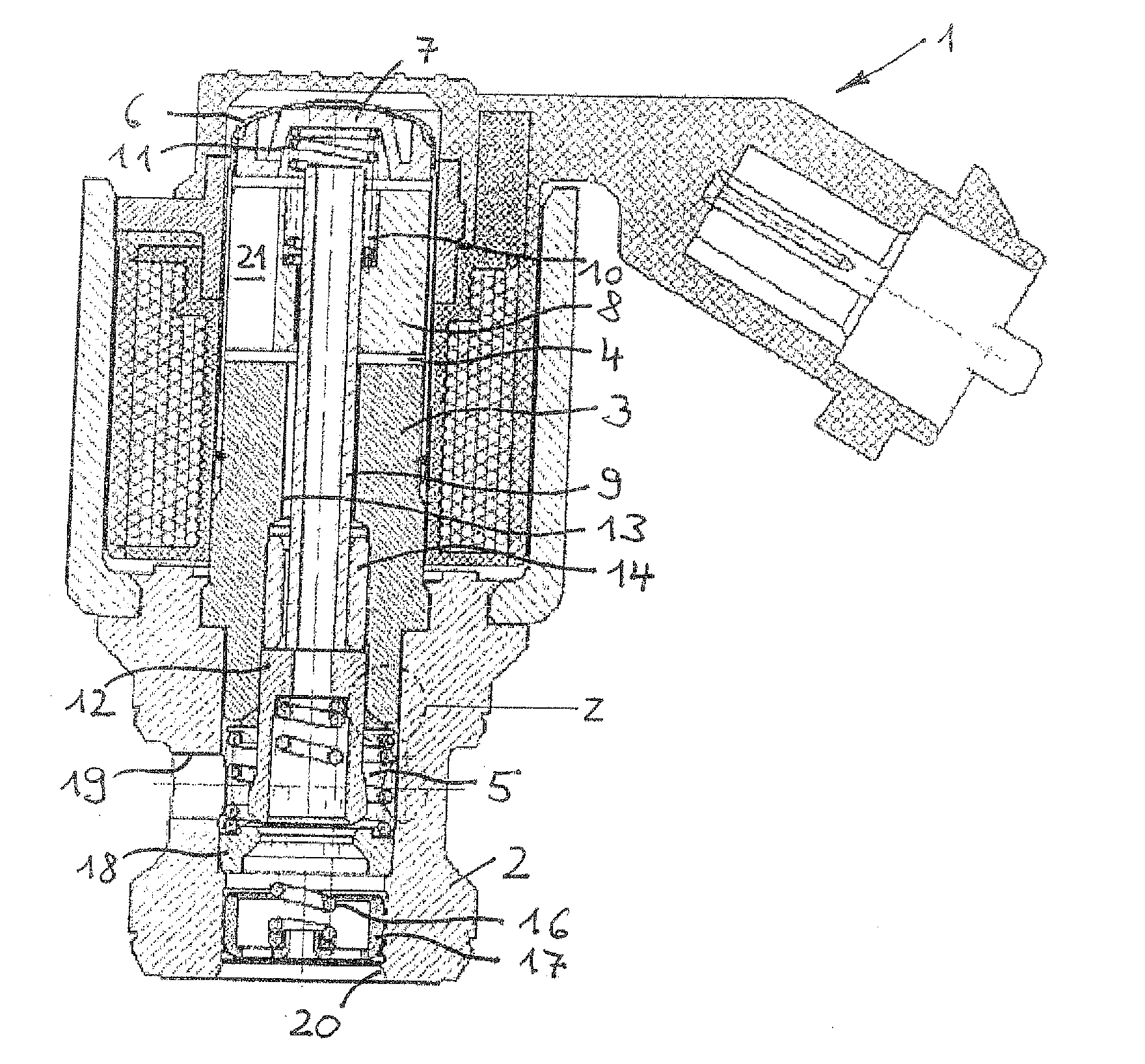
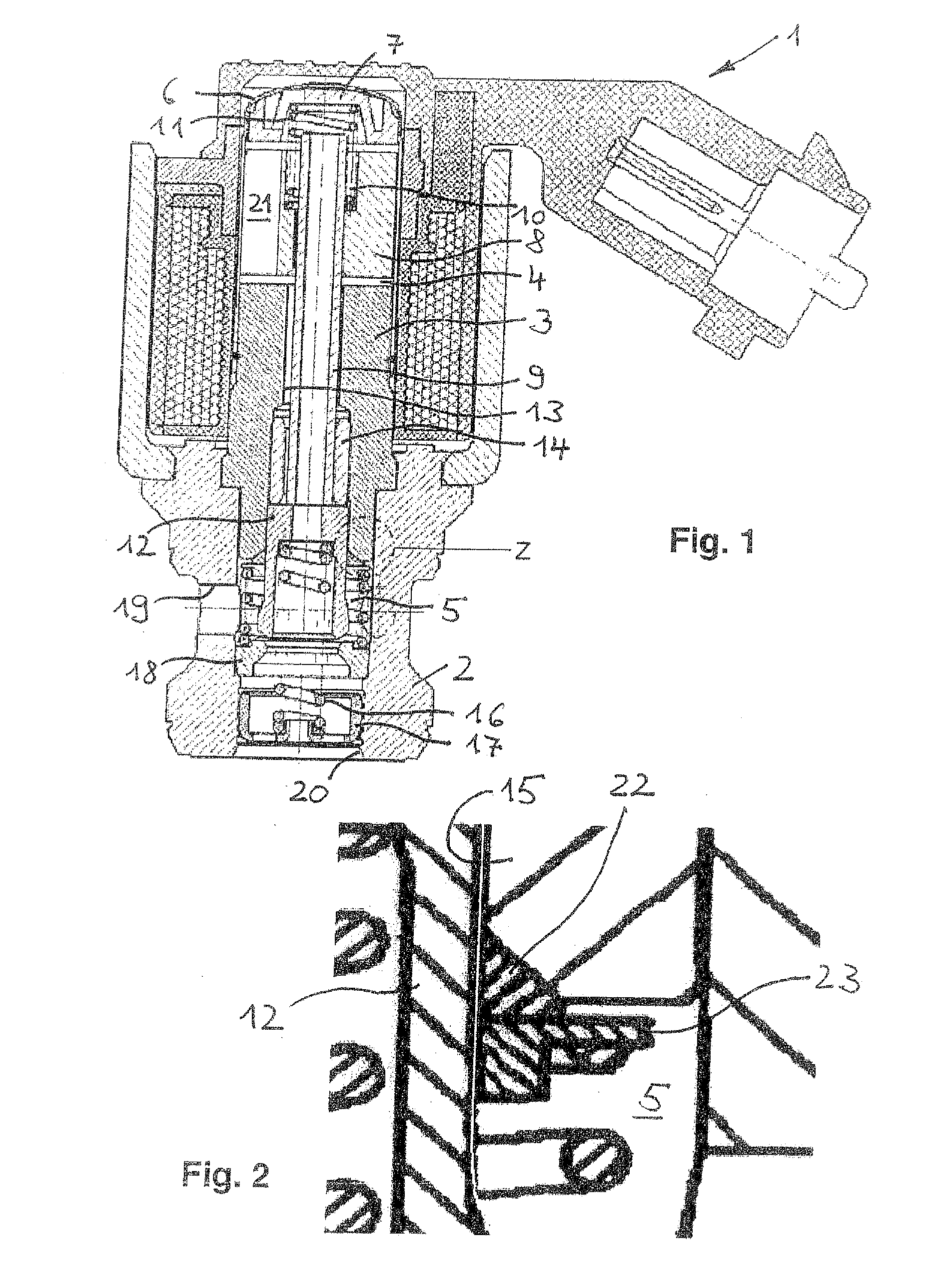
[0017]FIG. 1 shows, in longitudinal section, an electromagnetic valve 1 embodied as a 2 / 2-way scat valve. The electromagnetic valve 1 has a valve housing 2, which is embodied in the style of a cartridge and realized, in respect of production engineering, as a turned part suitable for automated machines. Inserted in the upper portion of the valve housing 2 is a tubular magnet core 3, which is fixed in a liquid-tight manner in the valve housing 2 by means of an outer caulking of the valve housing 2. Placed on the magnet core 3, which delimits, on the one hand, a magnet armature chamber 4 and, on the other hand, a pressure medium chamber 5, is its thin-walled sleeve 6, which is produced by a deep-drawing process and closed in the form of a cup in the end region, and which accommodates a solid end disk 7 in the end region. A magnet armature 8 disposed, beneath the end disk 7, so as to be movable in the sleeve 6 is connected to a tubular valve tappet 9...


PUM


Abstract

An electromagnetic valve, which has a magnet armature chamber, a pressure medium chamber, a pressure medium inlet channel and a pressure medium outlet channel respectively connected to the pressure medium chamber, a valve seat, and a valve closure member that, upon bearing contact on the valve seat, blocks the connection between the pressure medium inlet channel and the pressure medium outlet channel, and a valve guide extending between the magnet armature chamber and the pressure medium chamber. A sealing ring made of a polymer, which surrounds the valve closure member and separates the magnet armature chamber from the pressure medium chamber, extends between the valve closure member and the valve guide. The geometric design of the sealing ring to the valve guide provides wear resistance for the sealing ring.

Description

CROSS-REFERENCE TO RELATED APPLICATION[0001]This application claims the benefit of DE 10 2010 021 395.0 filed May 25, 2010, which is incorporated by reference herein.FIELD OF THE INVENTION[0002]The invention relates to an electromagnetic valve.BACKGROUND OF THE INVENTION[0003]In the case of such an electromagnetic valve, the sealing ring serves to minimize unwanted gap leakage flows through the clearance fit between the valve closure member and the valve guide in the direction of the magnet armature chamber and, consequently, of the hydraulic pressure equilibrium of the valve closure member. It is known for electromagnetic valves according to DE 10 2005 049 122 A1 or DE 10 2005 061 509 A1 to be provided with a scaling ring of polytetrafluoroethylene, referred to in short in the following as PTFE, whose contact surface with the valve guide has the surface shape of a spherical segment. As is known, the term spherical segment is to he understood as a geometric body that is produced by ...

Claims


Application Information

Patent Timeline
IPC IPC(8): F16K31/02
CPCF16K31/0693F16K31/0655
Inventor ITOAFA, CALIN PETRUKUFNER, ANDREAS
Owner SCHAEFFLER TECH AG & CO KG
Why Eureka
Try Eureka