
Refractive index distribution measuring method and refractive index distribution measuring apparatus

a technology of refractive index and measuring method, which is applied in the direction of instruments, applications, other domestic objects, etc., can solve the problems of low refractive index measurement accuracy, weak signal output of the detector,

Inactive Publication Date: 2011-12-01
CANON KK
View PDF8 Cites 20 Cited by
  • Summary
  • Abstract
  • Description
  • Claims
  • Application Information

AI Technical Summary

Benefits of technology

[0006]The present invention provides a refractive index distribution measuring method and a refractive index distribution measuring apparatus which can highly precisely measure a refractive index distribution of an object.

Problems solved by technology

However, the matching oil having a high refractive index has a low transmittance, and a detector can output only a weak signal.
Thus, the measuring precision of the object having a high refractive index is likely to lower.

Method used


Image

  • Refractive index distribution measuring method and refractive index distribution measuring apparatus
  • Refractive index distribution measuring method and refractive index distribution measuring apparatus
  • Refractive index distribution measuring method and refractive index distribution measuring apparatus

Examples


first embodiment

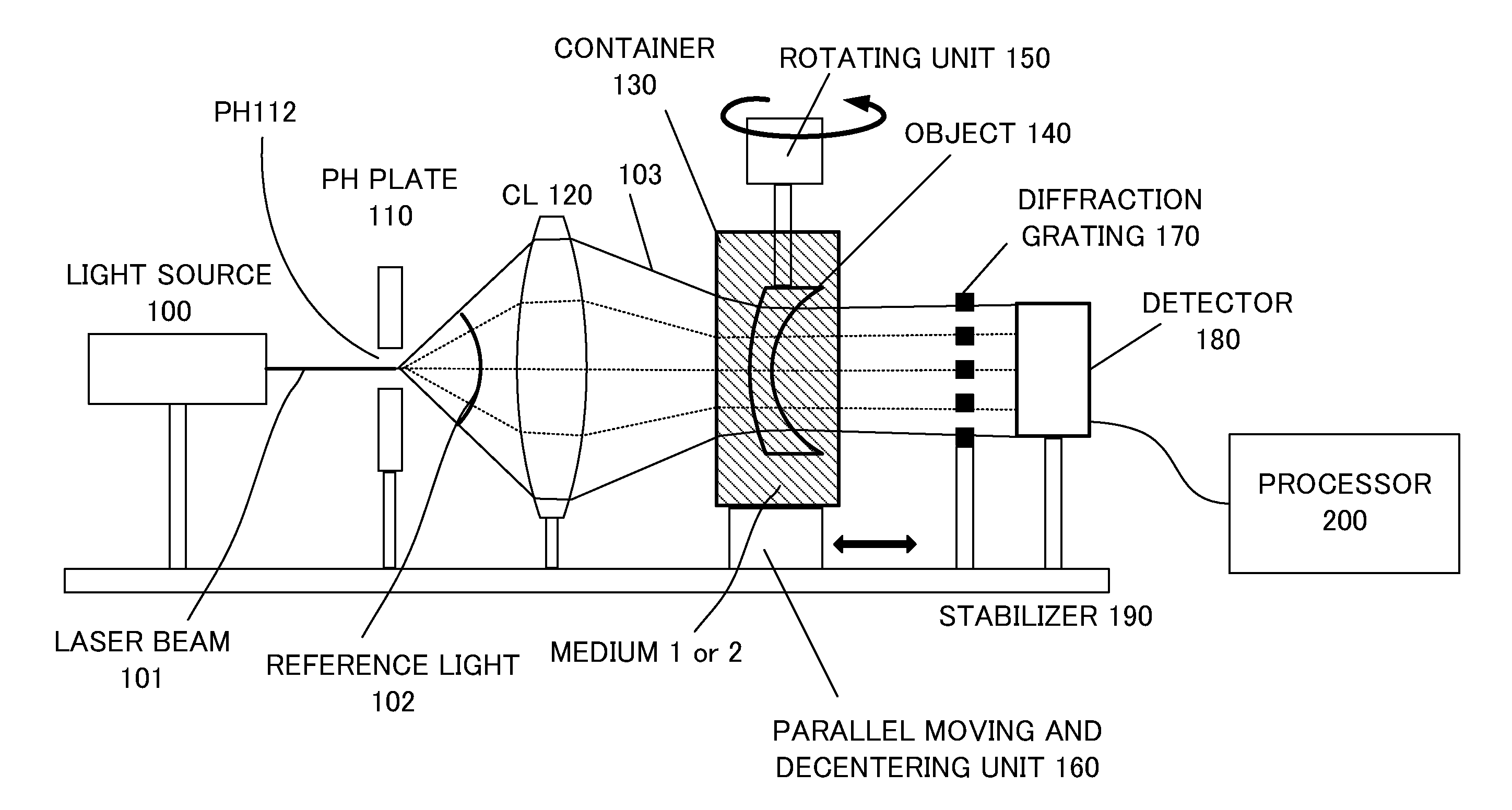
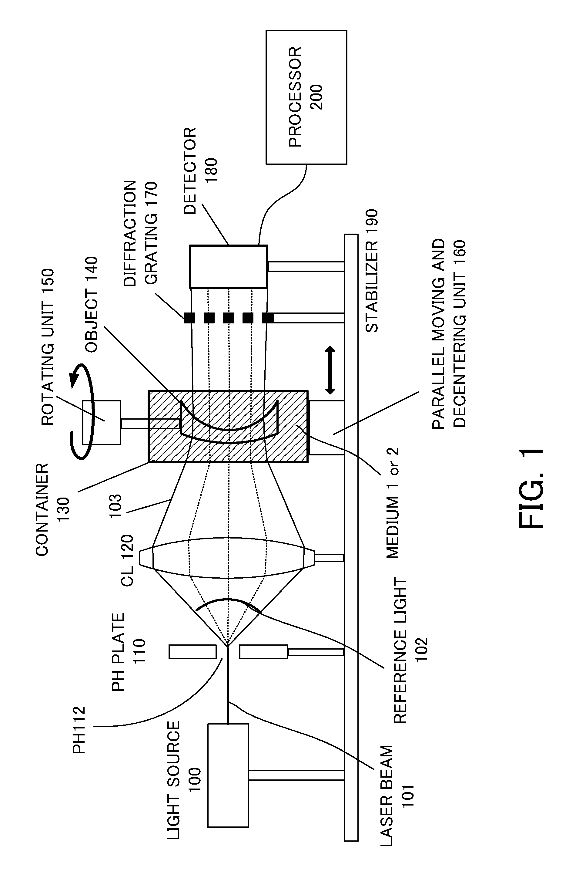
[0016]FIG. 1 is a block diagram of a refractive index distribution measuring apparatus installed on a stabilizer 190. The refractive index distribution measuring apparatus measures a transmitted wavefront of an object by immersing the object in each of two types of media, such as air and water, each of which has a refractive index different from that of the object and by introducing reference light from a light source into the object. The refractive index distribution measuring apparatus then calculates a refractive index distribution of the object utilizing a processor as a computer and a measurement result of the transmitted wavefront. This embodiment utilizes a Talbot interferometer as a measuring unit configured to measure the transmitted wavefront of the object arranged in the medium by utilizing the light from the light source.

[0017]The object 140 is an optical element, such as a lens. A container 130 houses a medium 1 such as air, or a medium 2 such as water. The refractive i...

second embodiment

[0063]FIG. 5 is a block diagram of a refractive index distribution measuring apparatus of the second embodiment. The refractive index distribution measuring apparatus of this embodiment finds a refractive index distribution by measuring the transmitted wavefront twice using two types of light sources and one type of medium M. The two types of light sources are, for example, a He—Ne laser (with a first wavelength of 633 nm) as a light source 100A and a second harmonic of a YAG laser (with a second wavelength of 532 nm different from the first wavelength) as a light source 100B.

[0064]The medium M has a refractive index different from that of the object 140. For example, the refractive index of the medium is smaller than that of the object, and larger than that of air. One example of the medium M is water, and low refractive index oil having a refractive index of about 1.5 to about 1.8.

[0065]The pinhole plate 110 generates (reference) light having the ideal spherical wave using a laser...


PUM

PropertyMeasurementUnit
refractive indexaaaaaaaaaa
diameteraaaaaaaaaa
diameteraaaaaaaaaa

Abstract

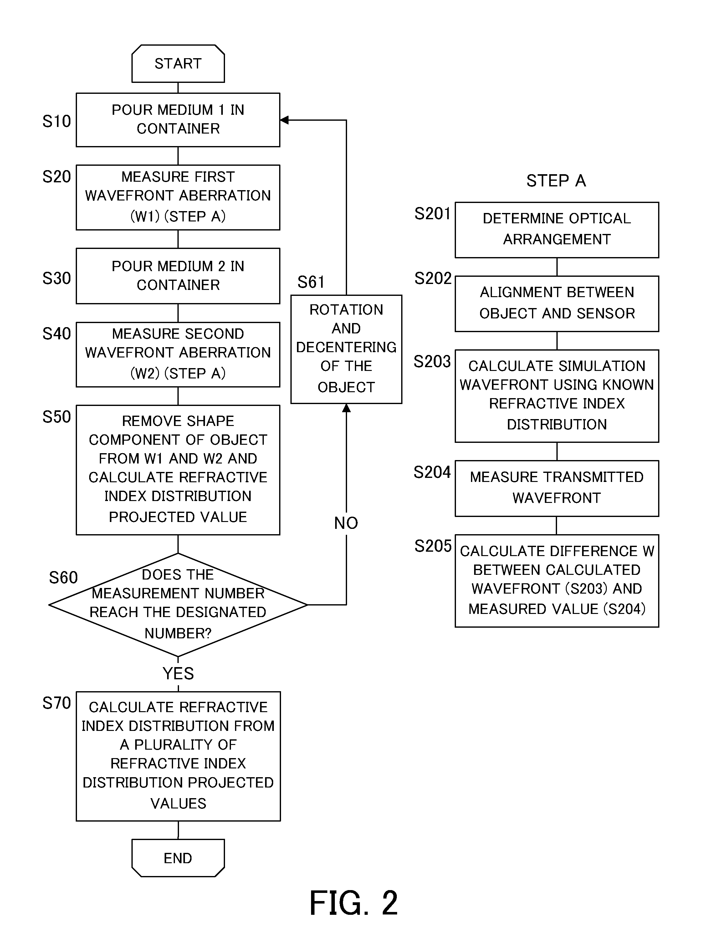
A method includes the steps of measuring a first transmitted wavefront in a first medium having a first refractive index and a second transmitted wavefront in a second medium having a second refractive index different from the first refractive index, and obtaining a refractive index distribution projected value of the object in each orientation by removing a shape component of the object utilizing measurement results of the first transmitted wavefront and the second transmitted wavefront and each transmitted wavefront of a reference object that has the same shape as that of the object and a specific refractive index distribution and is located in one of the first medium and the second medium with the same orientation as that of the object, and calculating a three-dimensional refractive index distribution of the object based on a plurality of refractive index distribution projected values corresponding to the plurality of orientations.

Description

BACKGROUND OF THE INVENTION[0001]1. Field of the Invention[0002]The present invention relates to a refractive index distribution measuring method and a refractive index distribution measuring apparatus.[0003]2. Description of the Related Art[0004]Japanese Patent Laid-Open No. (“JP”) 01-316627 proposes a method for finding a refractive index distribution of an object by measuring its transmitted wavefront while the object is immersed in a medium (matching oil) which has approximately the same refractive index as that of the object. JP 02-008726 proposes a method for finding a refractive index distribution of an object by measuring its transmitted wavefront while the object is immersed in each of two types of matching oils, which has a slightly different refractive index from that of the object.[0005]These methods disclosed in JPs 01-316627 and 02-008726 need matching oils each of which has approximately the same refractive index as that of the object. However, the matching oil having...

Claims


Application Information

Patent Timeline
Patent Type & Authority Applications(United States)
IPC IPC(8): G01N21/41B29D11/00
CPCG01M11/0228G01N21/45G01N21/41G01M11/02
Inventor KATO, SEIMA
Owner CANON KK
Learn More