
Method for mounting transparent component

a technology of transparent components and components, applied in the field of mounting transparent components, can solve the problems of difficult to capture an image of an outline of the lens component, the electrode extraction method cannot be employed, and the traditional image capturing method does not allow the captured image to show

Inactive Publication Date: 2011-12-01
MATSUSHIMA YOSHIHIKO +3
View PDF2 Cites 26 Cited by
  • Summary
  • Abstract
  • Description
  • Claims
  • Application Information

AI Technical Summary

Benefits of technology

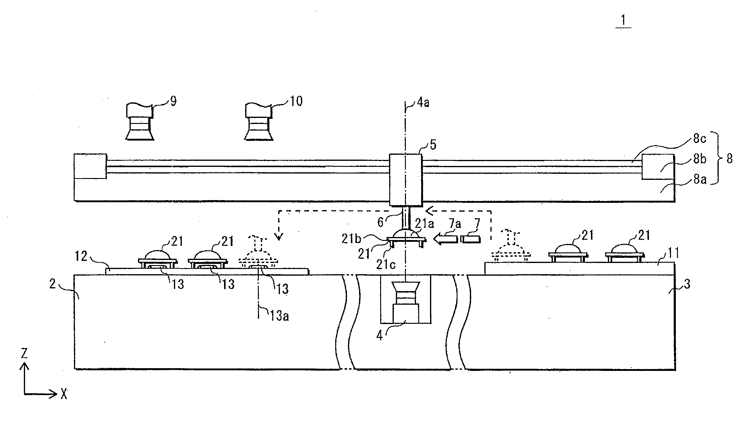
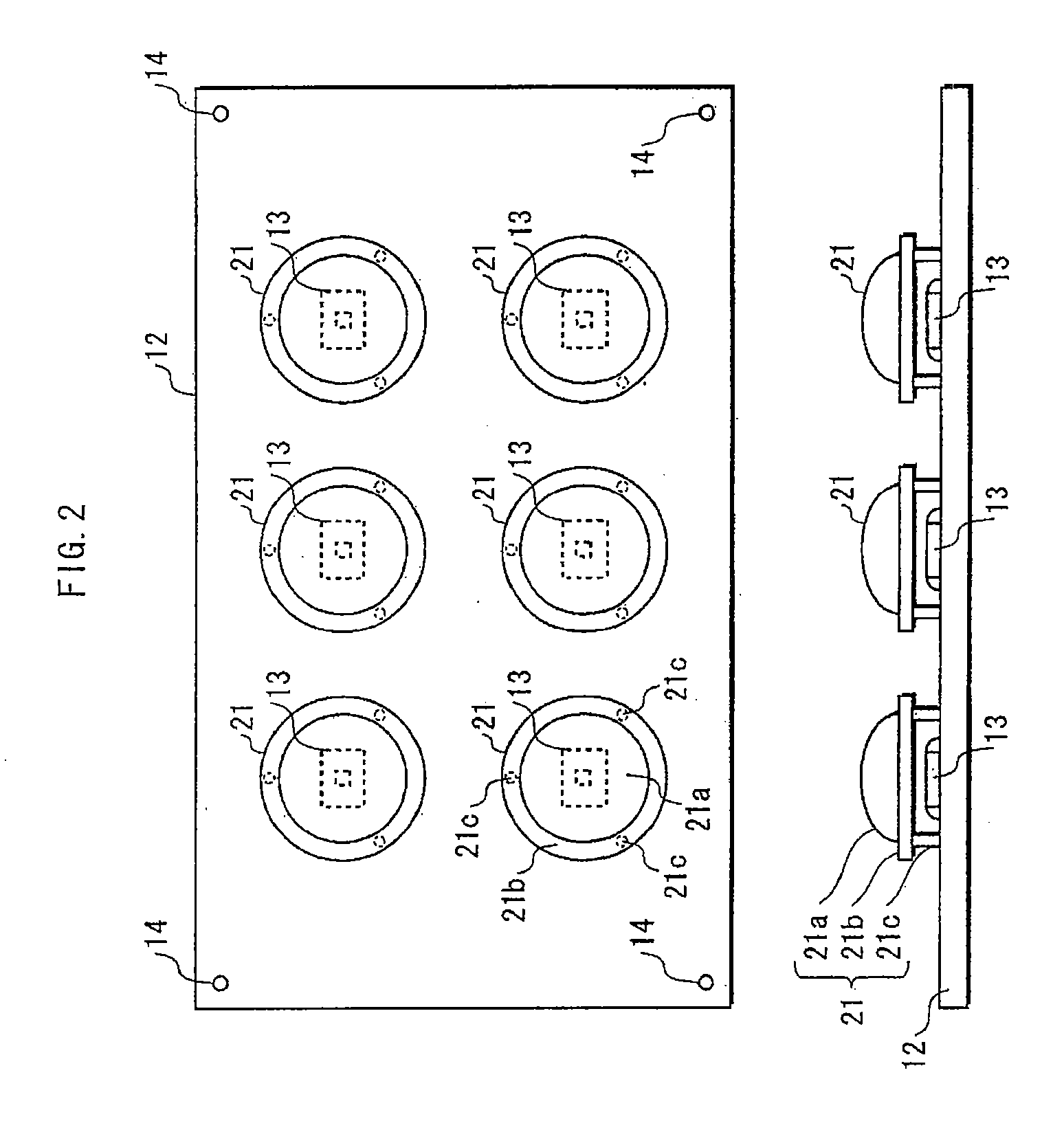
[0006]In recent years, productization of a certain type of light emitting module has been suggested—more specifically, a light emitting module manufactured by mounting a light emitting component (e.g., an LED component) and a lens component on a substrate in such a manner that the lens component covers the upper side of the light emitting component. Light distribution characteristics of this type of light emitting modules can be differentiated from one another, simply by constructing the light emitting modules with use of identical substrates, identical light emitting components, and different lens components. The advantage of the above method lies in being able to utilize identical light emitting components, yet providing various types of light emitting modules at low cost. To further increase the effect of cost reduction, it is desired in the future to manufacture light emitting modules more productively by using a surface mounter to mount lens components.
[0011]When a spotlight is irradiated onto the transparent component, the transmission, scattering, reflection, refraction, diffraction, etc. of the spotlight occurs while the spotlight is passing through the transparent component. Consequently, part of the spotlight travels toward the component recognition camera. By making the transparent component locally thick and / or thin, the amount of light transmitted therethrough toward the component recognition camera can be differentiated between the thick / thin parts and other part of the transparent component around the thick / thin parts. In the resultant captured image, the above difference is shown as a difference in local brightness levels, thus allowing to recognize the held state of the transparent component. As a result, the transparent component can be mounted precisely in the target position on the substrate.

Problems solved by technology

However, as an entirety of a lens component is transparent, it is difficult to capture an image of an outline of the lens component.
Moreover, as a lens component does not include electrodes, the electrode extraction method cannot be employed, either.
That is to say, the traditional image capturing methods do not allow the captured image to show characteristic features of such a transparent lens component.
This gives rise to the problem that the lens component cannot be mounted precisely in a target position on a substrate.
This problem is not limited to being associated with a lens component, but also applies to other transparent components such as a prism component.

Method used


Image

  • Method for mounting transparent component
  • Method for mounting transparent component
  • Method for mounting transparent component

Examples


modification examples

[0059]The above has described the method for mounting the transparent component based on the embodiment. However, the present invention is not limited to the embodiment, and may be implemented according to, for example, the following modification examples.

[0060](1) In the embodiment, only the leg portions 21c represent the thick parts that each have a large thickness in the vertical direction. However, the present invention is not limited to this structure. The transparent component may include other portions that also represent the thick parts, in addition to the leg portions.

[0061]FIG. 4 shows a lens component 22 including protruded portions 22d, which protrude upward from a plurality of areas in the top surface of an annulus portion 22b. As the protruded portions 22d represent the thick parts that each have a large thickness in the vertical direction, a captured image of the lens component 22 shows bright and dark spots. In the example shown in FIG. 4, the protruded portions 22d ...


PUM


Abstract

A transparent component locally includes one or both of a plurality of thick parts that have a large thickness in the vertical direction, and a plurality of thin parts that have a small thickness in the vertical direction. A component recognition camera captures an image of the transparent component held by a mount head, from above or below the transparent component, while a single spotlight or a plurality of spotlights are being irradiated onto the transparent component.

Description

BACKGROUND OF THE INVENTION[0001](1) Field of the Invention[0002]The present invention relates to technology for mounting a transparent component in a target position on a substrate by using a surface mounter.[0003](2) Description of the Related Art[0004]Conventionally, a surface mounter has been widely used to mount a chip component in a target position on a substrate. A surface mounter operates in the following manners. First, the surface mounter causes a component recognition camera to capture an image of a chip component held by a mount head. Secondly, the surface mounter recognizes a held state of the chip component from the captured image, the held state denoting the state in which the chip component is being held (the position of a part of the chip component that is being held, and the angle by which the chip component has rotated about its axis along a vertical reference line). Thirdly, the surface mounter adjusts the mount head in position according to the held state. (For ...

Claims


Application Information

Patent Timeline
Patent Type & Authority Applications(United States)
IPC IPC(8): G06K9/00
CPCH05K13/0413H05K13/0812
Inventor MATSUSHIMA, YOSHIHIKOKAWAKAMI, TADASHIIMAI, TOHRUTHUENCHAROEN, MONTIEN
Owner MATSUSHIMA YOSHIHIKO
Learn More