Method and Arrangement for Real-Time Difference Determination for Mobile Terminal Processing

a mobile terminal and real-time difference technology, applied in the field of telecommunication systems, can solve the problems of cost, resource consumption, implementation and management of td methods, and achieve the effect of improving the positioning of mobile terminals

Active Publication Date: 2011-12-01
TELEFON AB LM ERICSSON (PUBL)
View PDF2 Cites 10 Cited by
  • Summary
  • Abstract
  • Description
  • Claims
  • Application Information

AI Technical Summary

Benefits of technology

[0012]Advantages of the present disclosure include im

Problems solved by technology

TD methods are also costly and resour

Method used


Image

  • Method and Arrangement for Real-Time Difference Determination for Mobile Terminal Processing
  • Method and Arrangement for Real-Time Difference Determination for Mobile Terminal Processing
  • Method and Arrangement for Real-Time Difference Determination for Mobile Terminal Processing

Examples


first embodiment

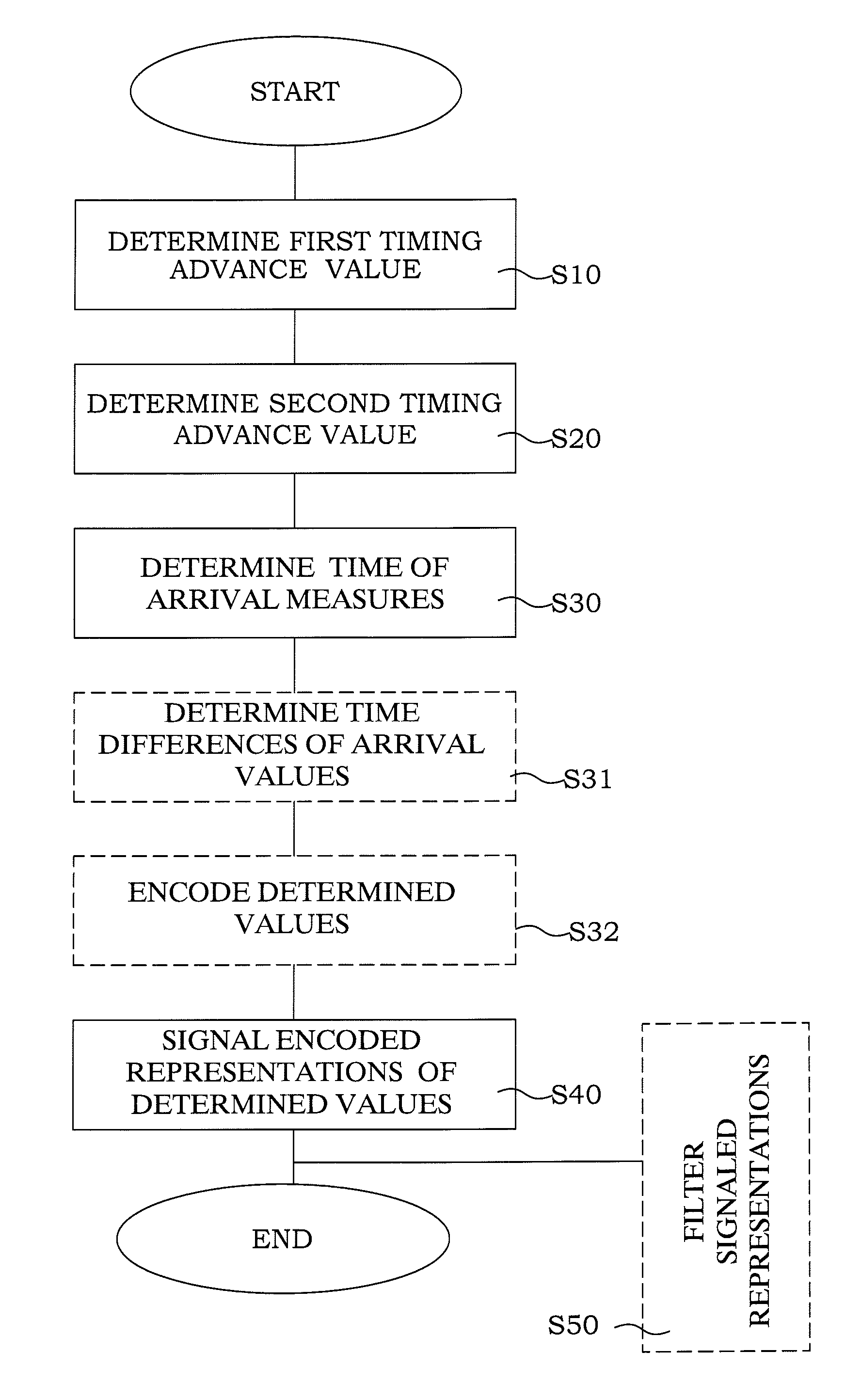
[0070]According to the present invention, a time of arrival (TOA) measurement is performed in association with the first and second TA measurements above. This measurement is according to Equation 12

tTOA:|ttTOA−tHandover|<TLimit   (12).

[0071]After measurement it is similarly encoded to give tTOA,Encoded. The encoded TOA measure is then signalled from the mobile terminal to the eNodeB over the RRC (LTE) interface, optionally together with the ID of the eNodeB (to provide a general signalling principle, allowing also for signalling of multiple measurements). i.e. as Equation 13

tTOA,Encoded, IDeNodeB   (13).

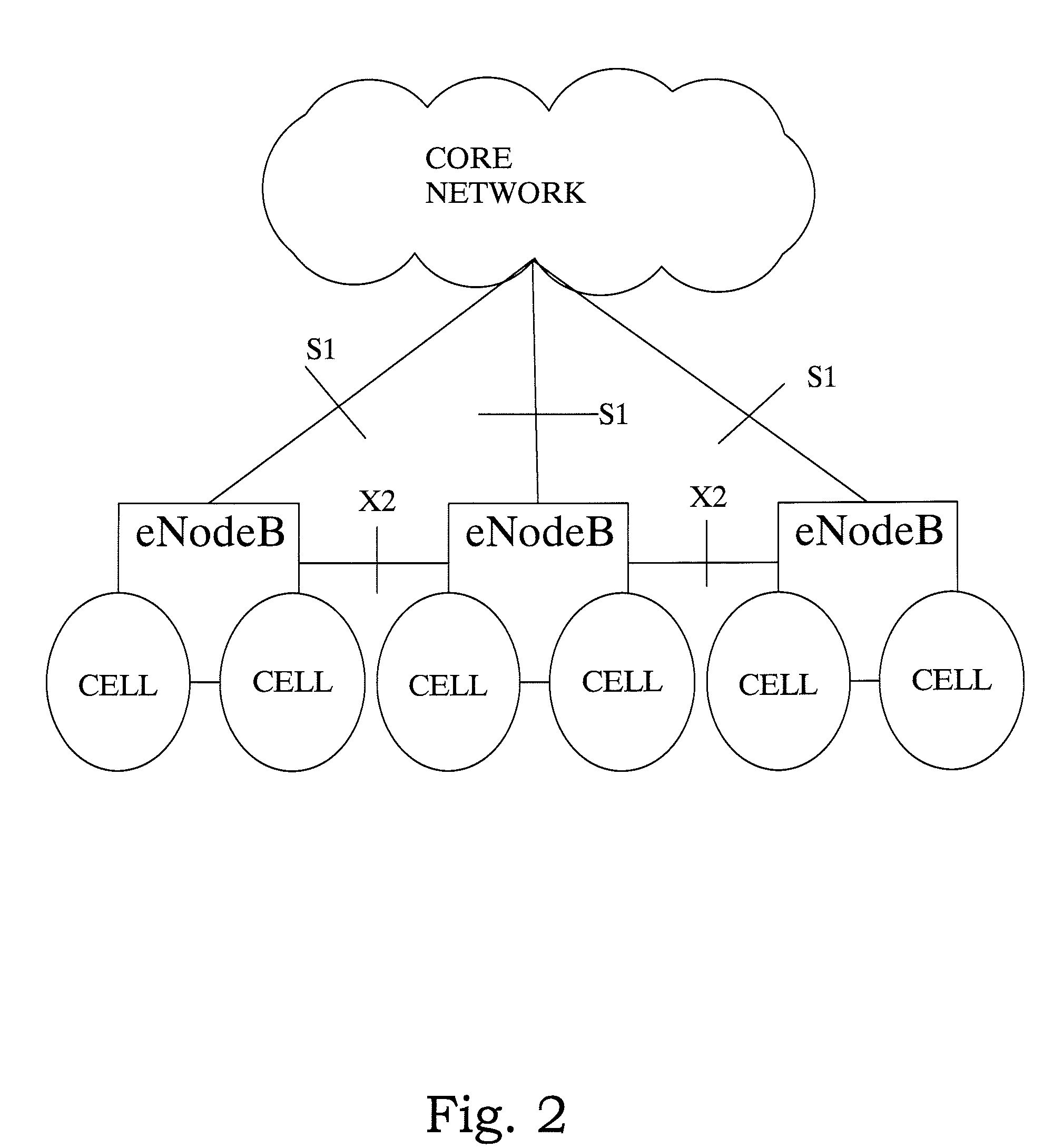
[0072]The information element received in the eNodeB may also be further signaled over the X2 interface to another eNodeB or to a position calculation node outside the LTE RAN.

Multiple TOA Measurements and Signalling

second embodiment

[0073]In a second embodiment, time of arrival (TOA) measurement with regard to several eNodeBs are performed in association with the TA measurements above. These measurements are according to Equation 14

tTOA,i:|ttTOA,i−tHandover<TLimit, i=1, . . . , NTOA,   (14)

where NTOA denotes the number of TOA measurements that are performed. After measurement the measurements are preferably encoded to give tTOA,i,Encoded, i=1, . . . , NTOA. The encoded measurements are subsequently signaled from the mobile terminal to the serving eNodeB over the RRC (LTE) interface, together with the IDs of the respective eNodeBs, i.e. as Equation 15

tTOA,i,Encoded, IDi,eNodeB, i=1, . . . , NTOA   (15).

[0074]The signalling could be performed either by repetition of the signalling of a single TOA, or in some list, defining a joint information element. The information element received in the eNodeB may also be further signalled over the X2 interface to another eNodeB or to a position calculation node outside th...

third embodiment

[0075]In a third embodiment, time of arrival measurement with regard to several eNodeBs are performed in association with the TA measurements above. These measurement are

tTOA,i:|ttTOA,i−tHandover|<TLimit, i=1, . . . , NTOA,   (16)

where NTOA denotes the number of TOA measurements that are performed. After measurement, the TOA measurements are processed to obtain TDOA (pseudo) measurements, with respect to one selected eNodeB. This gives the TDOAs

tTDOA,j=tTOA,j−tTOA,J, j=1, . . . , NTOA, j≠J.   (17)

[0076]The TDOAs are then encoded to givetTDOA,j,Encoded, j=1, . . . , NTOA, j≠J. They are then signalled from the terminal to the eNodeB over the RRC (LTE) interface, together with the IDs of the eNodeBs, i.e. as

IDJ,eNodeB; tTDOA,j,Encoded, IDj,eNodeB, j=1, . . . , NTOA, j≠J.   (18)

[0077]The information element received in the eNodeB may also be further signalled over the X2 interface to another eNodeB or to a position calculation node outside the LTE RAN.

Filtering of Time of Transmissio...


PUM


Abstract

In a method of providing real time difference determination for a mobile terminal in a telecommunication system, comprising a plurality of eNodeBs in communication with a core network, each eNodeB having a plurality of associated cells, each cell potentially servicing one or more mobile terminals, determining S1O a first timing advance value representative of a first geographical distance measure between the mobile terminal and a first serving eNodeB prior to a handover to a second serving eNode B, determining S20 a second timing advance value representative of a second geographical distance measure between the mobile terminal and the second eNodeB after the handover. Subsequently, determining S30 a time of arrival measure between the mobile terminal and at least two eNodeBs, and signaling S40 representations of the determined first and second geographical distance measures and the determined time of arrival measures for said mobile terminal to at least said second eNodeB, together with a respective unique identification parameter of the at least two eNodeBs, wherein determination of real time differences is enabled based on at least the signaled representations.

Description

TECHNICAL FIELD[0001]The present invention relates to telecommunication systems in general, specifically to improved position determination of mobile terminals in long time evolution (LTE) cellular telecommunication systems.BACKGROUND[0002]The possibility to determine the position of a mobile device has enabled application developers and wireless network operators to provide location based, and location aware, services. Examples of those are guiding systems, shopping assistance, friend finder and other information services giving the mobile user information about their surroundings.[0003]In addition to the commercial services, the governments in several countries have also put requirements on the network operators to be able to determine the position of an emergency call. For instance, the governmental requirements in USA (FCC E911) requires that it must be possible to determine the position of a certain percentage of all emergency calls, with a pre-specified accuracy and within a p...

Claims


Application Information

Patent Timeline
IPC IPC(8): H04W36/32H04W64/00
CPCG01S5/10H04W64/00H04W36/08G01S5/14
Inventor WIGREN, TORBJORNKANGAS, ARI
Owner TELEFON AB LM ERICSSON (PUBL)
Why Eureka
Try Eureka