Network system, controller, and network control method

a network system and controller technology, applied in the field of network system control, can solve the problems of original appliances that cannot detect the completion of a session, cannot always protect sessions from being disconnected, and cannot be stopped for a long time, so as to achieve efficient appliance switching

Inactive Publication Date: 2011-12-01
NEC CORP
View PDF3 Cites 133 Cited by
  • Summary
  • Abstract
  • Description
  • Claims
  • Application Information

AI Technical Summary

Benefits of technology

[0019]An objective of the present invention is to provide a technique for efficiently switching appliances, while preventing an existing session from being disconnected.
[0028]The present invention efficiently attains switching of appliances, while preventing an existing, flow from being disconnected.

Problems solved by technology

When an original appliance is stopped and its function is reassigned to a different appliance to switch appliances to be used, this causes the following problems:
Thus, when there are many clients which use continuous connections, the original appliance cannot be stopped for a long time.
In addition, an appliance cannot detect the completion of a session with regard to a client which does not explicitly carry out a disconnecting process.
However, the period of the non-communication state is different depending on applications, and thus the uniform judgment based on timeout cannot always protect sessions from being disconnected.
Such mechanism cannot be used in many cases in a situation in which appliance models of a plurality of venders are simultaneously used.

Method used


Image

  • Network system, controller, and network control method
  • Network system, controller, and network control method
  • Network system, controller, and network control method

Examples


Embodiment Construction

[0046]The embodiment of the present invention will be described below with reference to the attached drawings.

1. Configuration

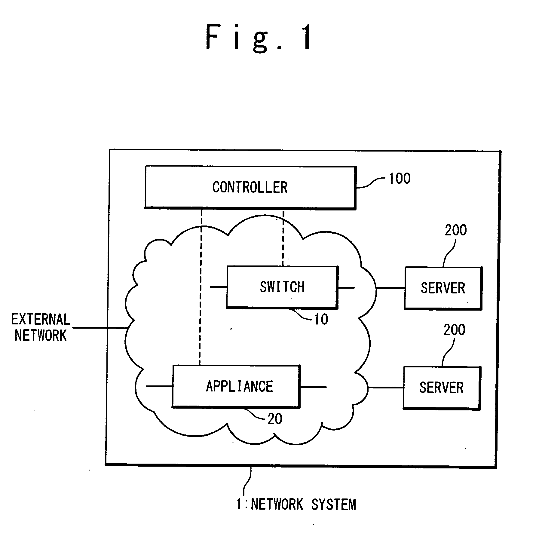
[0047]FIG. 1 is the block diagram schematically showing the configuration of a network system 1 according to an embodiment. The network system 1 according to this embodiment may be applied to, for example, a data center.

[0048]The network system 1 includes switches 10 (one shown), appliances 20 (one shown), a controller 100 and servers 200. The switches 10 and the appliances 20 configure a switch-appliance network. The servers 200 are connected to the switch-appliance network. The switch-appliance network is further connected to an external network outside the network system 1. The controller 100 is connected to the switches 10 and the appliances 20 through control lines (shown by dashed lines in FIG. 1).

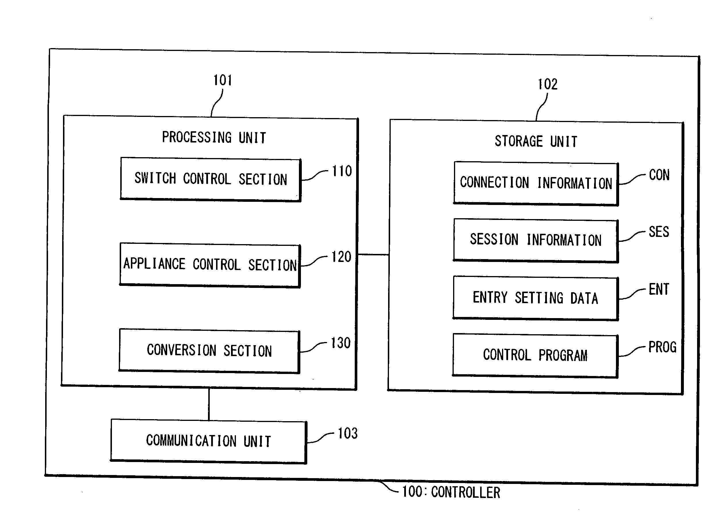
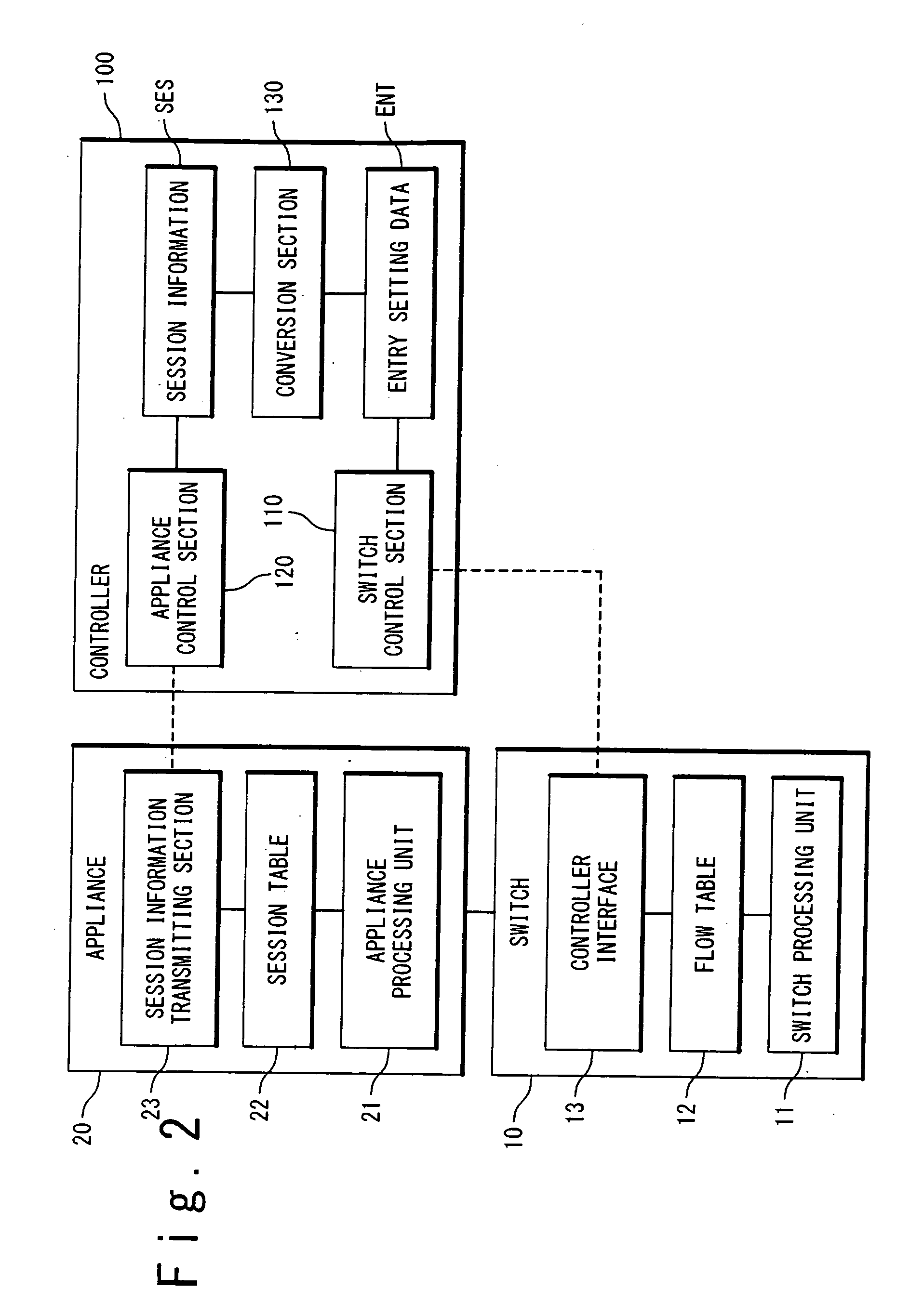
[0049]FIG. 2 shows the respective functional configurations of the switches 10, the appliances 20 and the controller 100 according to this embodiment. Each co...


PUM


Abstract

A network system includes appliances provided in a network; a switch provided in the network; and a controller connected to the appliances and the switch. The switch contains a flow table. Entries in the flow table each specify an action to be performed on a packet matching with a matching condition. Upon receiving a packet, the switch refers to the flow table and performs the action specified by matching one of the entries which matches the received packet, on the received packet. A first appliance of the appliances performs a first packet process on a packet belonging to an existing flow, when being selected as an active appliance. When the active appliance is switched from the first appliance to a second appliance of the appliances, the controller performs a switching process after performing a shortcut process. In the shortcut process, the controller instructs the switch to set a first entry into the flow table, the first entry specifying that the first packet process is to be performed on a packet belonging to the existing flow. In the switching process, the controller instructs the switch to set a second entry into the flow table, the second entry specifying that a packet which is addressed to the active appliance and belongs to a new flow other than the existing flow is to be transferred to the second appliance.

Description

CROSS-REFERENCE TO RELATED APPLICATION[0001]This is a continuation of International Application No. PCT / JP2011 / 051360, filed on Jan. 25, 2011.BACKGROUND OF THE INVENTION[0002]1. Field of the Invention[0003]The present invention relates to a technique for controlling a network system that includes an appliance. In particular, the present invention relates to a technique for switching appliances to be used.[0004]2. Description of the Related Art[0005]An appliance (network appliance) is a network apparatus specialized for a particular function, which is introduced into a network. Examples of an appliance include a load balancer and a firewall.[0006]A load balancer provides the function of a load distribution. In detail, a load balancer is recognized as a virtual server from an external network, and a client issues a request by specifying a virtual IP address (VIP) and a port number which correspond to this virtual server. The load balancer selects one real server which actually provide...

Claims


Application Information

Patent Timeline
Patent Type & Authority Applications(United States)
IPC IPC(8): G06F15/173
CPCH04L12/4625H04L45/38H04L12/66
Inventor AIDA, TAKAFUMI
Owner NEC CORP
Why Eureka
Try Eureka