Centrifugal dirt separation configurations for household-type and shop-type vacuum cleaners

a vacuum cleaner and centrifugal technology, which is applied in the direction of vacuum cleaners, vortex flow apparatus, cleaning filter means, etc., can solve the problems of preventing any weight reduction options, long shafts, and unsatisfactory positions for providing suction, so as to improve the desirability of the vacuum cleaner, the effect of convenient service and maintenan

Active Publication Date: 2011-12-08
KAH JR CARL L C
View PDF7 Cites 70 Cited by
  • Summary
  • Abstract
  • Description
  • Claims
  • Application Information

AI Technical Summary

Benefits of technology

[0012]It is an object of the present invention to provide an apparatus for separating particles from a fluid

Problems solved by technology

This position is not ideal for providing suction to lift dirt from the floor.
Having a long shaft through the cyclone separator chamber, however, as suggested by the referenced patent, would no

Method used


Image

  • Centrifugal dirt separation configurations for household-type and shop-type vacuum cleaners
  • Centrifugal dirt separation configurations for household-type and shop-type vacuum cleaners
  • Centrifugal dirt separation configurations for household-type and shop-type vacuum cleaners

Examples


Embodiment Construction

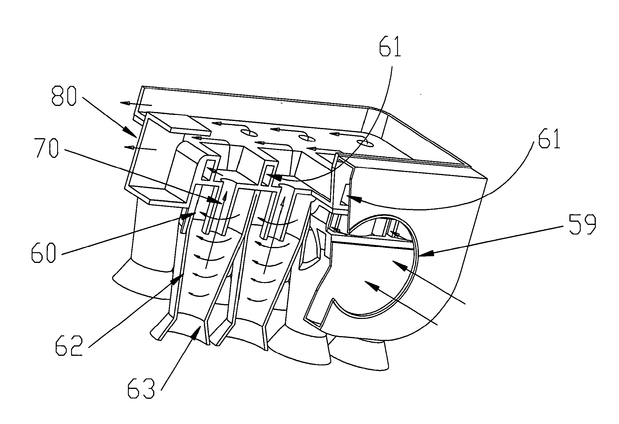
[0046]The theory of cyclone dirt or dust separation suggests that efficiency can be increased by increasing the tangential velocity of the air in the separation chamber. This would typically suggest providing a more powerful motor to create a higher rate of fluid flow. However, there are limits to the size and weight of motors that the market will tolerate for domestic vacuum chambers, since the size and weight of these chambers naturally influences the size and weight of the resulting domestic home vacuum cleaner as a whole. Increased complexity and size also add to the cost of the vacuum cleaner, which is also an important consideration in the competitive home vacuum cleaner market.

[0047]Thus, reducing the size of the motor required to provide a simple high efficiency domestic home vacuum cleaner or shop vacuum cleaner is very desirable. Smaller, lighter weight, more energy efficient vacuum cleaners provide significant advantages in such a competitive market. The vacuum cleaner of...


PUM

PropertyMeasurementUnit
Diameteraaaaaaaaaa
Distanceaaaaaaaaaa
Velocityaaaaaaaaaa

Abstract

A cyclonic separation device in accordance with an embodiment of the present application preferably includes a first cyclone chamber having a cylindrical shape with a predetermined diameter, the first cyclone chamber including, a tangential inlet positioned on a first longitudinal end of the first cyclone chamber, a baffle plate positioned in the first cyclone chamber a predetermined distance from the tangential inlet, a tangential dirt outlet positioned on a second end of the cyclone chamber, opposite the inlet and on an opposite side of the baffle plate from the tangential inlet and a center exit duct mounted in the center of the cyclone chamber having an inlet opening positioned upstream from the baffle plate such the centrifuged fluid without particles flows into the center exit duct and out of the cyclone chamber.

Description

CROSS-REFERENCE TO RELATED APPLICATIONS[0001]The present application is a continuation of U.S. nonprovisional application Ser. No. 12 / 074,438 filed Mar. 8, 2008 entitled CENTRIFUGAL DIRT SEPARATION CONFIGURATIONS FOR HOUSEHOLD-TYPE AND SHOP-TYPE VACUUM CLEANERS which claims benefit of and priority to U.S. Provisional Patent Application Ser. No. 60 / 892,723 filed Mar. 2, 2007 entitled CENTRIFUGAL DIRT SEPARATION CONFIGURATIONS FOR HOUSEHOLD-TYPE AND SHOP-TYPE VACUUM CLEANERS, the entire contents of which are hereby incorporated by reference herein.BACKGROUND[0002]1. Field of the Disclosure[0003]The present application relates to an apparatus for separating dirt or dust particles from an air flow by cyclonic means. The application relates particularly, but not exclusively, to a cyclonic dust separation apparatus for use in a vacuum cleaner.[0004]2. Related Art[0005]Cyclone dust separation devices typically include a frusto-conical (truncated cone) cyclone having a tangential air inlet ...

Claims


Application Information

Patent Timeline
IPC IPC(8): A47L9/16B01D50/00B01D45/16
CPCA47L5/14A47L9/0477A47L9/1608A47L9/1641A47L9/1683B01D45/16B04C2009/005B04C5/04B04C5/103B04C5/14B04C5/185B04C2009/004B01D50/002B01D50/20
Inventor KAH, JR., CARL L.C.
Owner KAH JR CARL L C
Why Eureka
Try Eureka