Pipette Tip Positioning For Manually-Directed, Multi-Channel Electronic Pipettor

a technology of electronic pipette and pipette head, which is applied in the direction of fluid controllers, instruments, laboratory glassware, etc., can solve problems such as instability, and achieve the effect of aligning accuracy

Active Publication Date: 2011-12-08
INTEGRA BIOSCI CORP
View PDF2 Cites 20 Cited by
  • Summary
  • Abstract
  • Description
  • Claims
  • Application Information

AI Technical Summary

Benefits of technology

[0008]If the user loads a 96-well plate onto the nesting receptacle on the deck, the user must first align the pipetting head and pipette tips with the 96-wells in the plate before dropping downward into the wells to aspirate or dispense. The biasing mode assists the user to properly align the pipetting channels and tips. Alignment accuracy is particularly important when aspirating or dispensing from a 384-well plate because the dimension of the wells is so much smaller than with a typical 96-well plate. If desired, the biasing mode can be activated independently for each nesting receptacle.

Problems solved by technology

Without the biasing mode, the accumulated force of 96 pipette tips touching off simultaneously against a wall of the wells in a wellplate can create instability.

Method used


Image

  • Pipette Tip Positioning For Manually-Directed, Multi-Channel Electronic Pipettor
  • Pipette Tip Positioning For Manually-Directed, Multi-Channel Electronic Pipettor
  • Pipette Tip Positioning For Manually-Directed, Multi-Channel Electronic Pipettor

Examples


Embodiment Construction

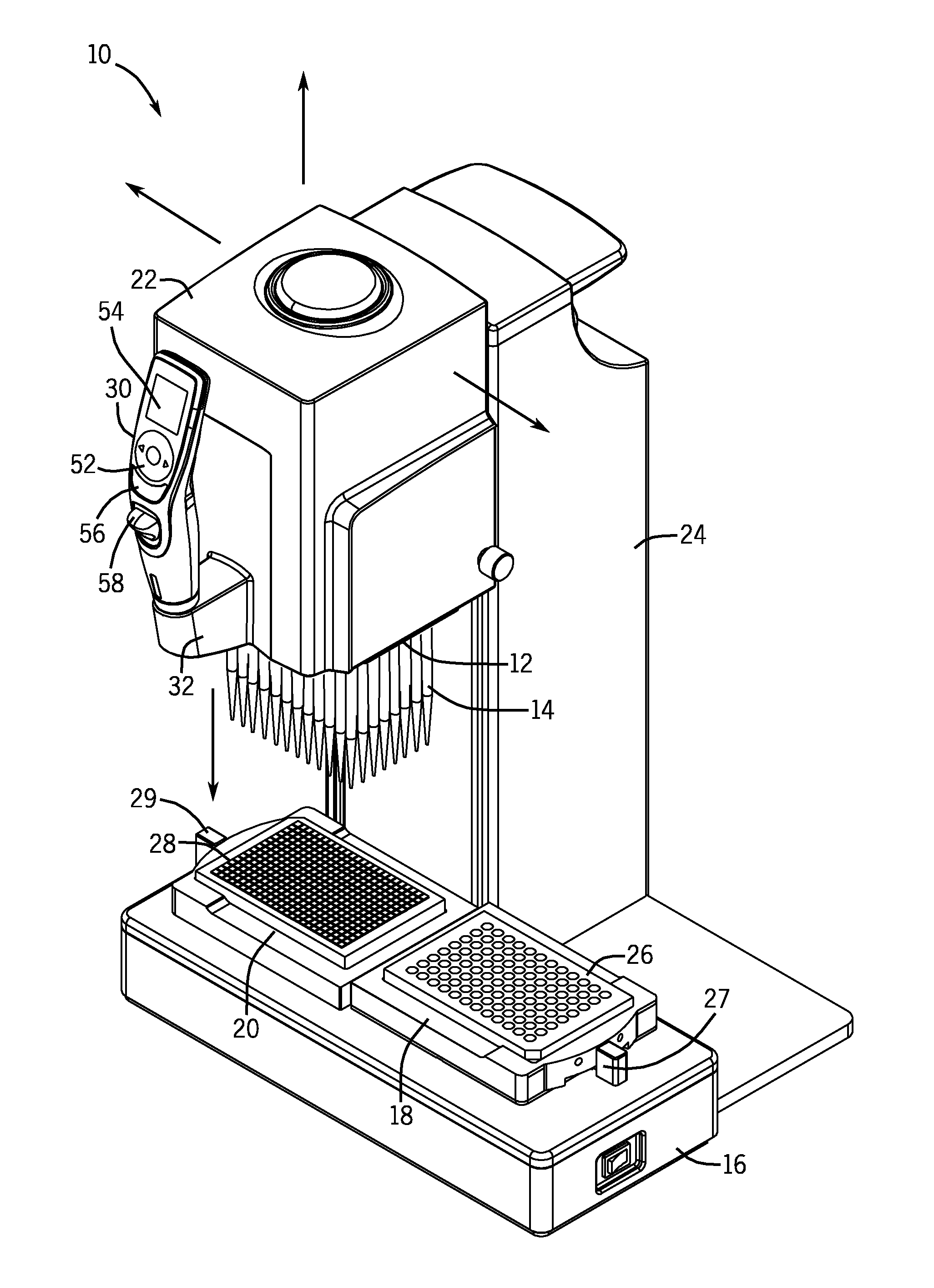
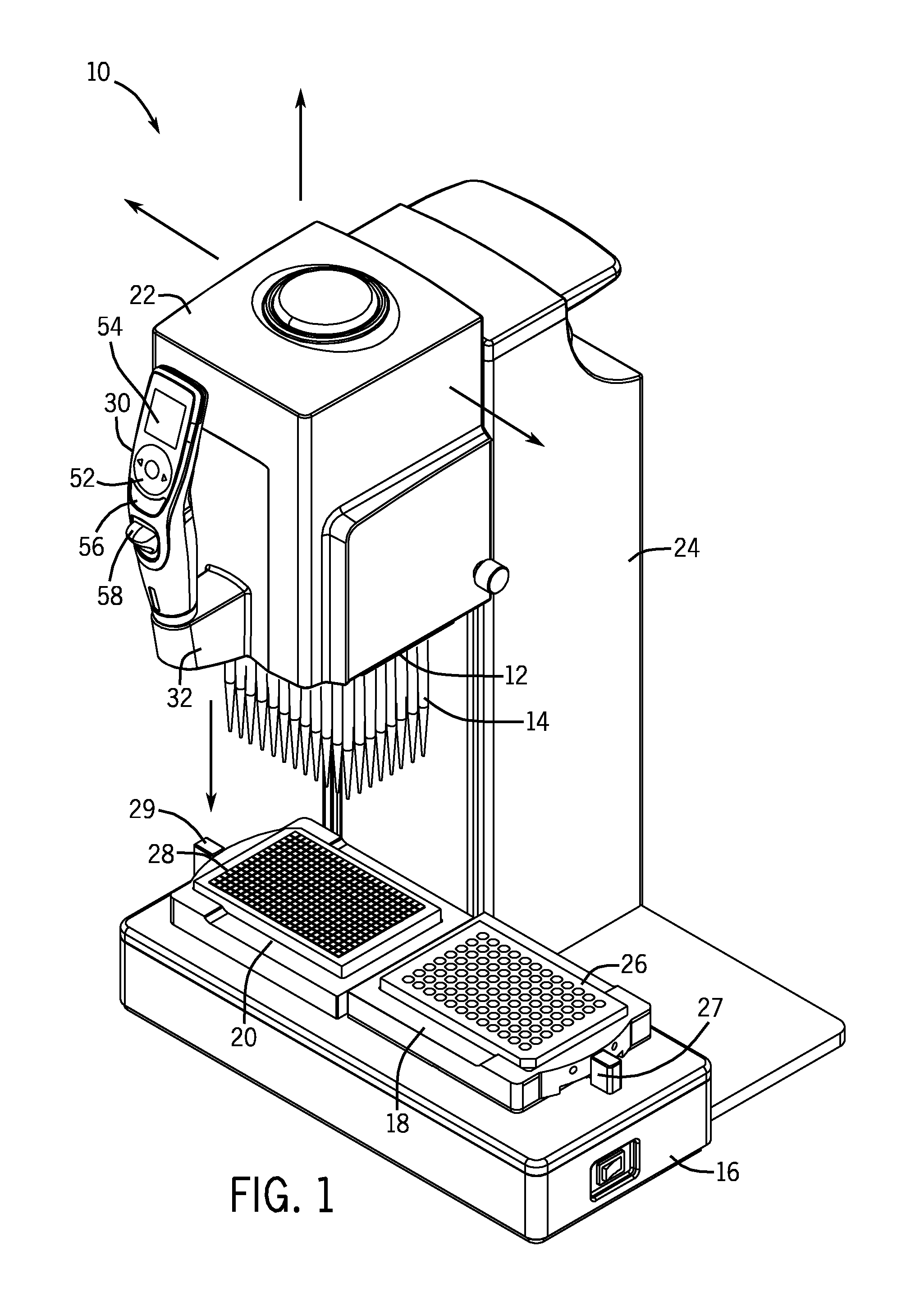
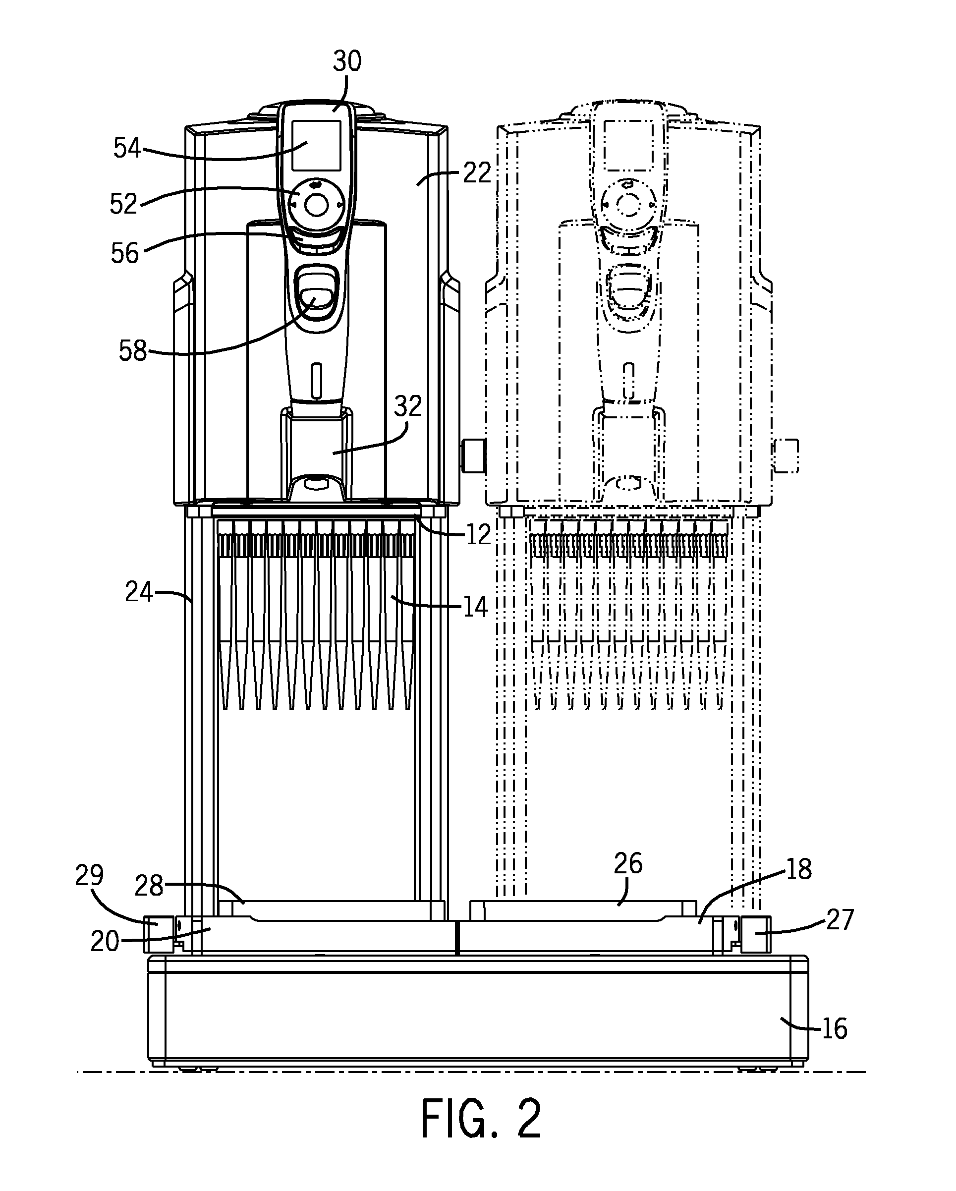
[0019]An embodiment of a manually directed, multi-channel electronic pipetting system 10 as described in the above incorporated patent applications is shown in FIGS. 1 and 2. Referring to FIGS. 1 and 2, the manually directed, multi-channel electronic pipetting system 10 includes a multi-channel pipetting head 12 having a plurality of pipetting channels arranged in a two dimensional array of rows and columns. Normally, the pipetting head 12 will include an array of 96-tip fittings. An array of pipette tips 14 are attached to the multi-channel pipetting head 12. The manually directed, multi-channel electronic pipetting system 10 includes a flat deck 16 supporting a right nesting receptacle 18 and a left nesting receptacle 20. The nesting receptacles 18, 20 are designed to hold multi well-plates or reservoirs in a known location on the deck 16. In FIGS. 1 and 2, a 96-well plate 26 is located in the right nesting receptacle 18. A 384-well plate 28 is located in the left nesting receptac...


PUM


Abstract

A manually directed, multi-channel electronic pipettor includes a software biasing mode to assure proper alignment over wells in the 96-well plate and the 384-well plate. The system also includes manual repositioning levers for nesting receptacles which are customized for 96 well-plates and 384 well-plates respectively.

Description

FIELD OF THE INVENTION[0001]The invention relates to a manually directed, electronic pipetting system having a pipetting head with a plurality of pipetting channels, e.g., 96-channels, arranged in an array of rows and columns. In particular, the invention pertains to methods of positioning the pipetting head for simultaneous aspiration and dispensing of liquid samples and reagents from multi well-plates.BACKGROUND OF THE INVENTION[0002]The assignee of the present application has filed a co-pending patent application entitled “Manually-Directed, Electronic Multi-Channel Electronic Pipetting System”, which was filed on even date herewith, by Julian Warhurst, Gary Nelson and Richard Cote, is based on U.S. Provisional Application No. 61 / 330,541, filed on May 3, 2010, and is herein incorporated by reference. The assignee has also filed another co-pending patent application entitled “Unintended Motion Control for Manually Directed Multi-Channel Electronic Pipettor, which was filed on even...

Claims


Application Information

Patent Timeline
Patent Type & Authority Applications(United States)
IPC IPC(8): B01L3/02
CPCB01L3/0227B01L3/0234B01L3/0237B01L2200/025B01L2400/0487B01L2200/14B01L2300/027B01L2300/0829B01L2200/087
Inventor WARHURST, JULIAN
Owner INTEGRA BIOSCI CORP
Why Eureka
Try Eureka