
Brewing Device With Ground Coffee Quantity Control and Coffee Machine Comprising Such a Device

Inactive Publication Date: 2011-12-08
SEB SA
View PDF36 Cites 22 Cited by
  • Summary
  • Abstract
  • Description
  • Claims
  • Application Information

AI Technical Summary

Benefits of technology

[0016]Thus, by mechanically driving the potentiometer for only a portion of the stroke of the piston corresponding to the measurement range of the tamping position, it is possible to use a standard, simple, reliable, very economical component while achieving a high degree of measurement accuracy. In other words, the measurement range of the tamping position is adjusted to the working stroke of the potentiometer.
[0018]This arrangement allows for a very inexpensive component, as the rotary potentiometer is a standard component, manufactured in very large numbers.
[0020]This arrangement provides for an extremely simple construction with which to control the potentiometer, consisting, for example, of two simple plastic parts.
[0022]This arrangement provides a simple, economical method of returning the potentiometer into position.
[0027]This arrangement provides for a simple, inexpensive solution for the braking of the axis and also reinforces the seal of the potentiometer.

Problems solved by technology

However, several parameters can affect the amount of ground coffee supplied for a given rotation time of the grinding wheel, such as the amount of wear of the grinding wheels or the hardness of the coffee beans.
However, in this construction, the sensors and associated moving parts are expensive and sophisticated and can lead to failures.
In particular, an optical sensor is susceptible to contamination in the environment surrounding an espresso machine.
While the use of a linear potentiometer appears less expensive than the use of the other sensors mentioned above, it is nevertheless an expensive, bulky component that is difficult to automatically install on an electronic board.
Thus, the mechanics of the brewing device become quite complicated.
In addition, since the linear potentiometer has a long stroke, the seal provided by a standard component may be unreliable in the context of a coffee machine.

Method used


Image

  • Brewing Device With Ground Coffee Quantity Control and Coffee Machine Comprising Such a Device
  • Brewing Device With Ground Coffee Quantity Control and Coffee Machine Comprising Such a Device
  • Brewing Device With Ground Coffee Quantity Control and Coffee Machine Comprising Such a Device

Examples


Embodiment Construction

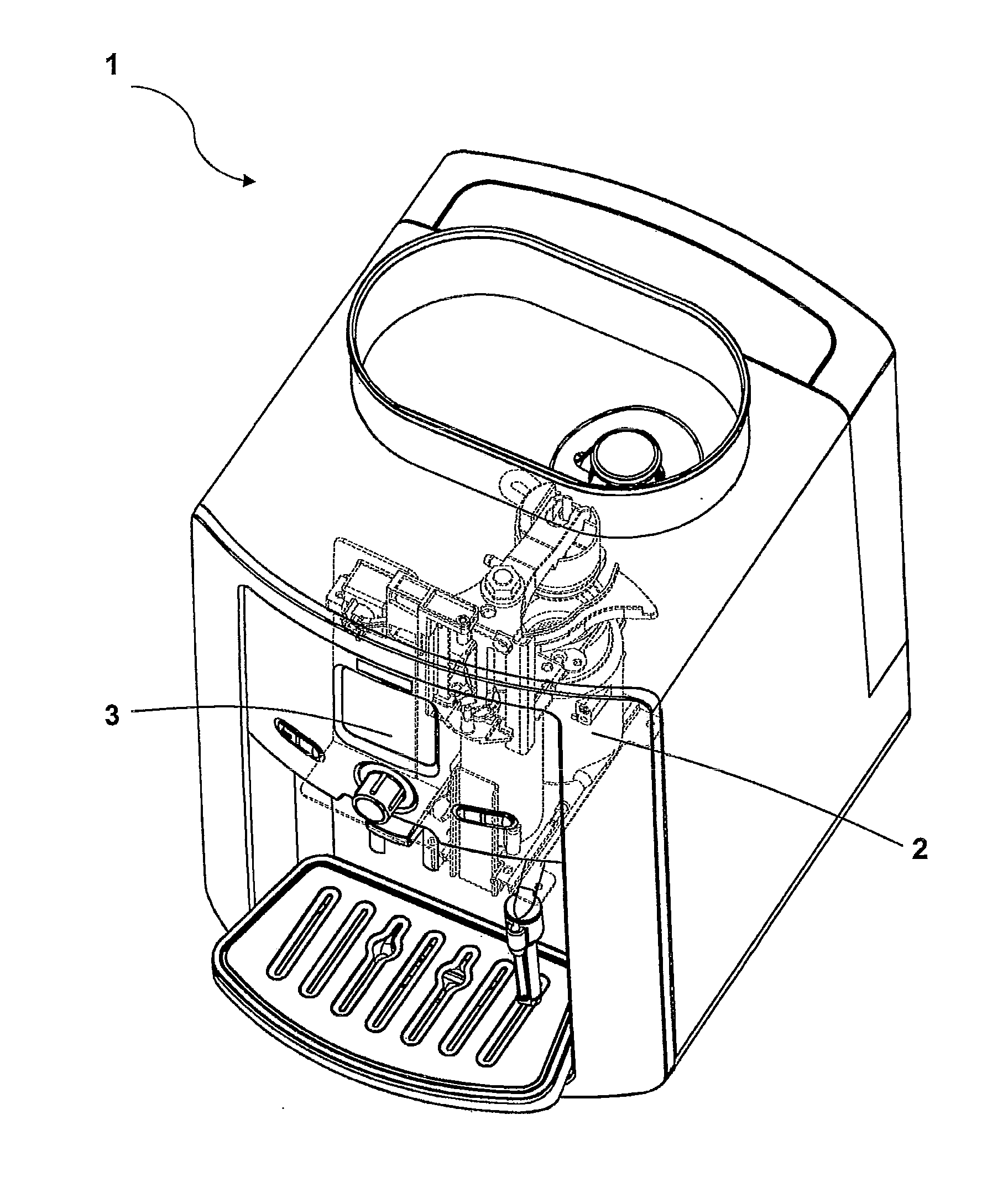
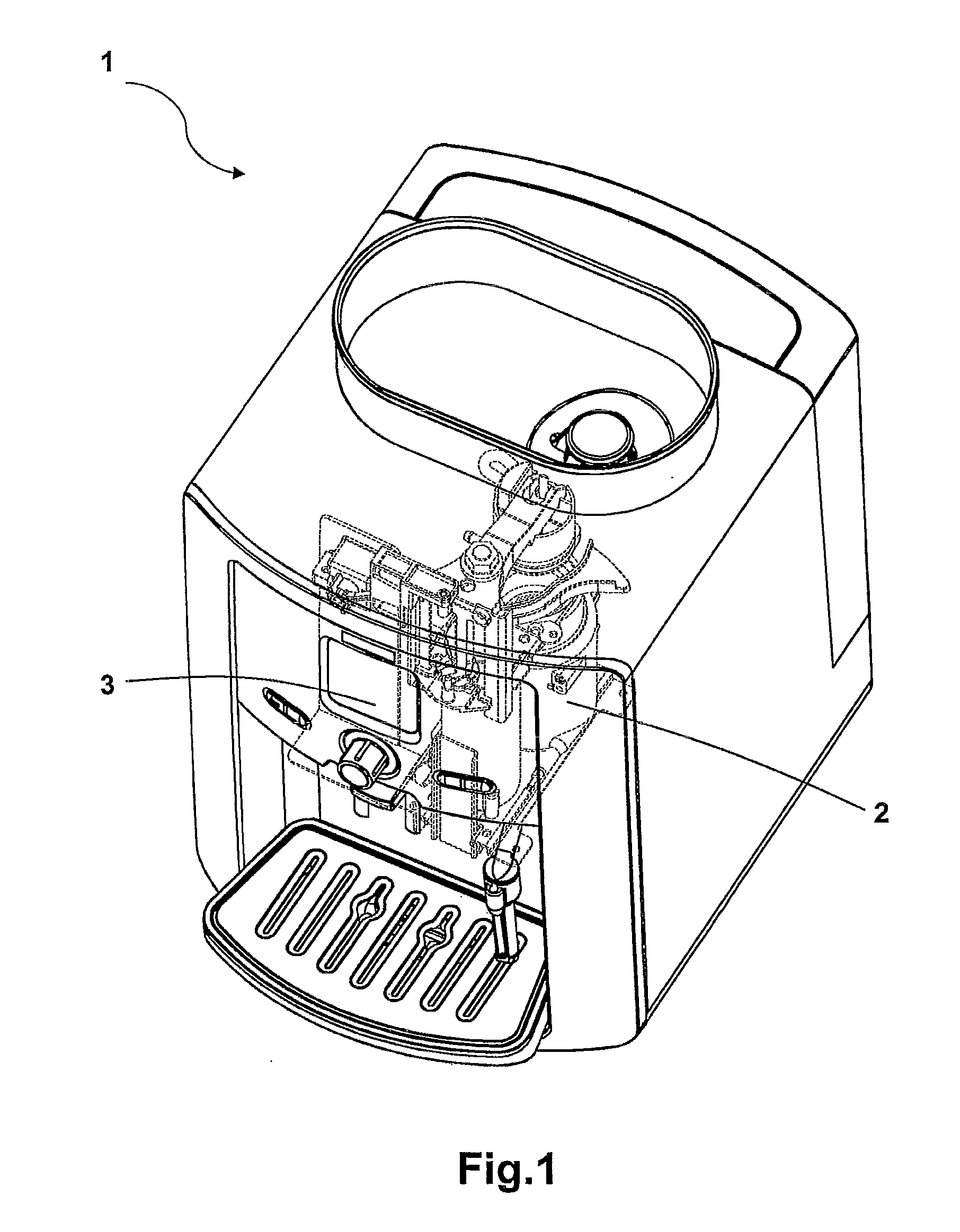
[0039]In the embodiment illustrated in FIG. 1, a brewing device 2 is intended to equip an automatic coffee machine 1 comprising a cold water supply, a dispenser of ground coffee from a coffee grinder integrated with the dispenser (not shown in the figures) and an electronic control device 3 for controlling and managing the brewed beverage preparation cycles.

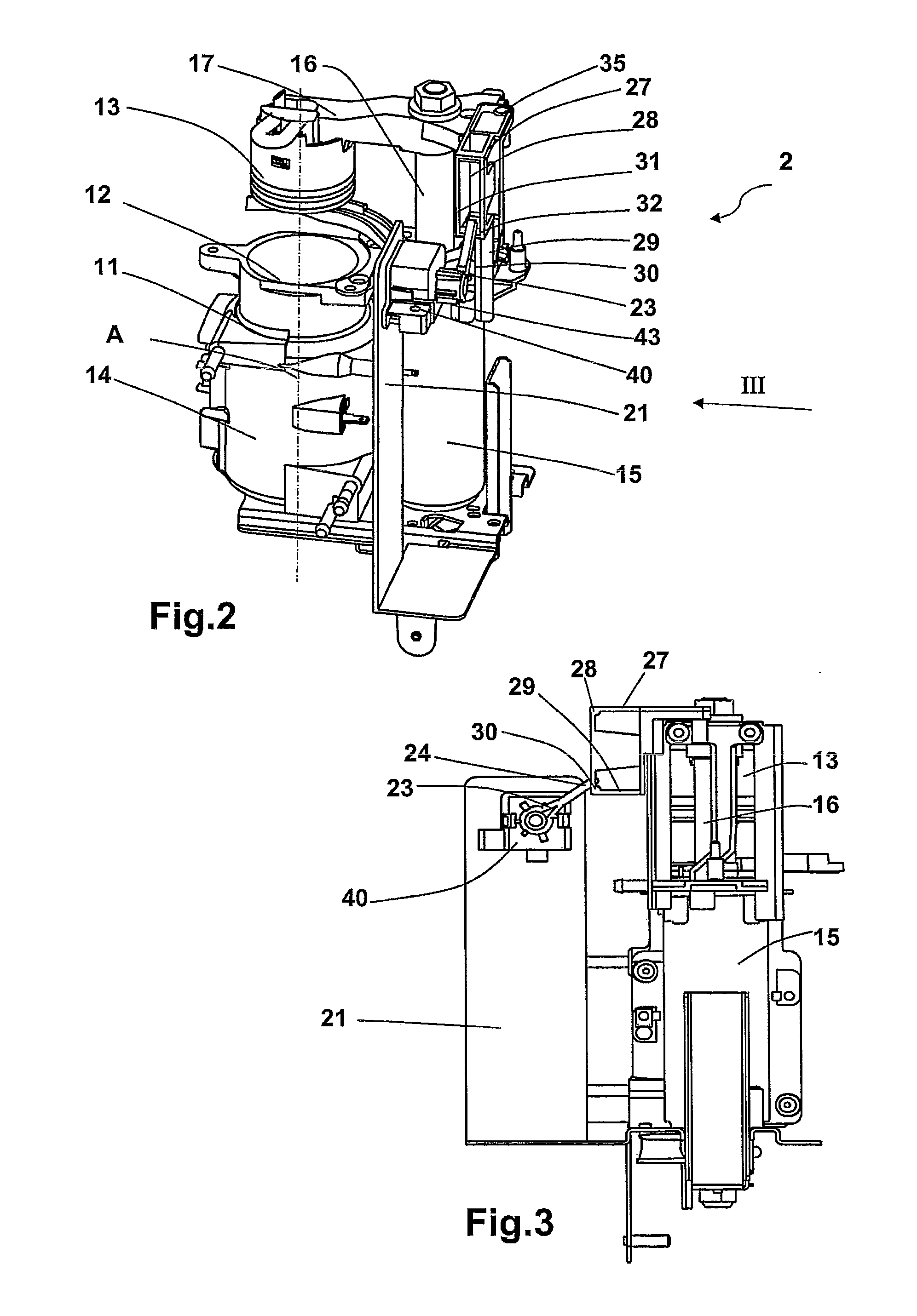
[0040]Such a brewing device 2 illustrated in FIGS. 2 through 6 comprises, in particular, a body 11 with a vertical longitudinal axis containing a brewing chamber 12 that is able to receive a pressure piston 13 that is movably mounted along axis A by means of a driving mechanism, pumping means (not shown) to circulate the water and the coffee, and a boiler 14 to heat the water to prepare the coffee in the brewing chamber 12. According to a particular, yet non-restrictive, characteristic of the invention, the body 11 is arranged laterally to a single-acting hydraulic cylinder 15 comprising an upper rod 16 supporting an arm 17 formi...


PUM


Abstract

A brewing device (2) for an espresso-type coffee machine including a brewing chamber (12) for receiving ground coffee, a movably mounted pressure piston (13) in translation with a stroke that extends from an upper retracted position in which the pressure piston (13) is located above the brewing chamber (12) to a lower tamping position in which the pressure piston (13) enters said brewing chamber (12) and a potentiometer controlled by driving means during the stroke of the pressure piston (13) to measure the tamping position of said pressure piston and to thereby calculate the height of the compressed cake of ground coffee. The driving means only act on the potentiometer for a portion of the stroke of the pressure piston (13).

Description

BACKGROUND OF THE INVENTION[0001]1. Field of the Invention[0002]The present invention relates to a brewing device for an espresso-type coffee machine, in particular a brewing device in which an amount of ground coffee introduced into a brewing chamber is controlled during each cycle to ensure consistent results for a selected beverage type.[0003]2. Description of the Prior Art[0004]The amount of ground coffee to be introduced into the brewing chamber can be varied to obtain different beverages including a strong espresso known as a ristretto, espresso, a weaker espresso known as a lungo, etc.[0005]Usually, the brewing device of a coffee machine comprises a brewing chamber that is supplied with ground coffee and a pressure piston that compresses the ground coffee in the brewing chamber into a cake. Generally, the ground coffee is produced by a coffee grinder equipped with grinding wheels, one of which is rotated. The amount of ground coffee supplied corresponds to a rotation time of ...

Claims


Application Information

Patent Timeline
IPC IPC(8): A47J31/40
CPCA47J31/3609A47J31/3614
Inventor VITEL, ARNAUDLEBUFFE, GILLESGAILHARD, THIERRY
Owner SEB SA
Learn More