
Cutting board excellent in a drainage function

a drainage function and cutting board technology, applied in the field of cutting boards, can solve the problems of water spilling over the floor, difficult to place the cutting board on the sink, and no water passage through which to pass, and achieve excellent drainage function, sufficient bearable strength, and maintained hygienic

Inactive Publication Date: 2011-12-08
NISHIDA KUNIHIKO
View PDF1 Cites 3 Cited by
  • Summary
  • Abstract
  • Description
  • Claims
  • Application Information

AI Technical Summary

Benefits of technology

The solution ensures effective water drainage, prevents bacterial growth, and provides a secure, adjustable fit on different sink sizes and shapes, maintaining hygiene and convenience during use.

Problems solved by technology

Since such a cutting board is so structured that opposed side surfaces of the cutting board are directly set in upper steps of the sink, there are no sufficient space through which water on the cutting board is drained into an interior of the sink.
Therefore, in a case where a person cooks or washes a surface of the cutting board with water running, there arises a problem in which water may spills out over the floor.
However, there is such a drawback that this cutting board is available only to such a sink having a width suitable for a distance between the leg sections.
It will also be difficult to place the cutting board on the sink having supporting steps of a curved shape on a sink top for the cutting board (see FIG. 7), since the leg sections are not made separately and thus their lengths are not independently adjustable.
Such a cutting board, however, has a limit in sizing holes and grooves, since the strength of the supporting sections decrease as the width of the holes and the grooves becomes large if the cutting board is made of wood or plastic.
There also has been such a problem that a workable area of the cutting board becomes narrower if the holes and the grooves are positioned near to a center of the cutting board in order to avoid such a problem that the holes and the grooves may be hidden in the width of steps of the sink if the steps of the sink on which the cutting board is placed is wide.

Method used


Image

  • Cutting board excellent in a drainage function
  • Cutting board excellent in a drainage function
  • Cutting board excellent in a drainage function

Examples


Embodiment Construction

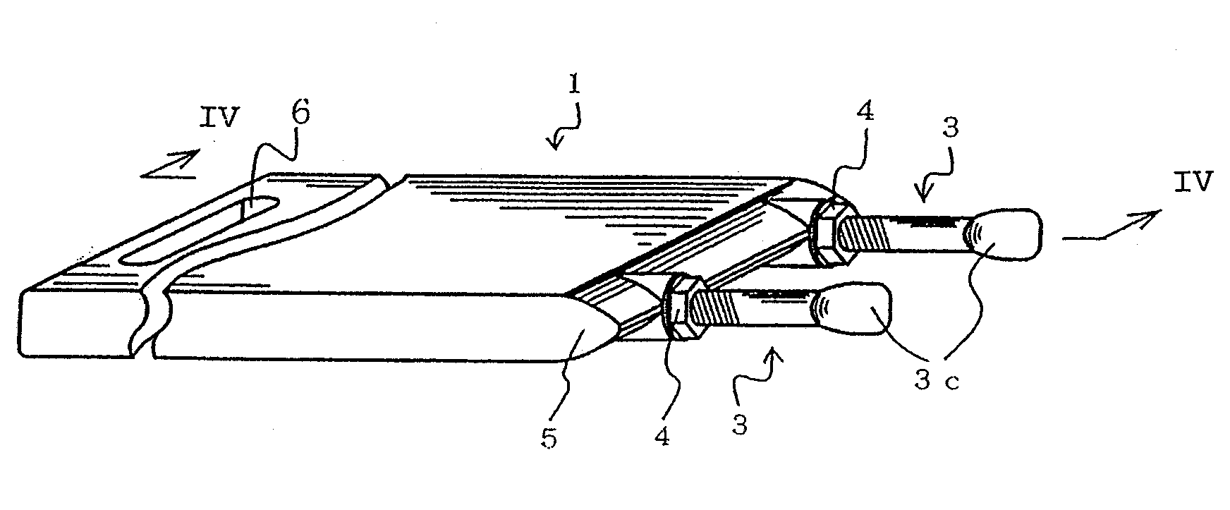
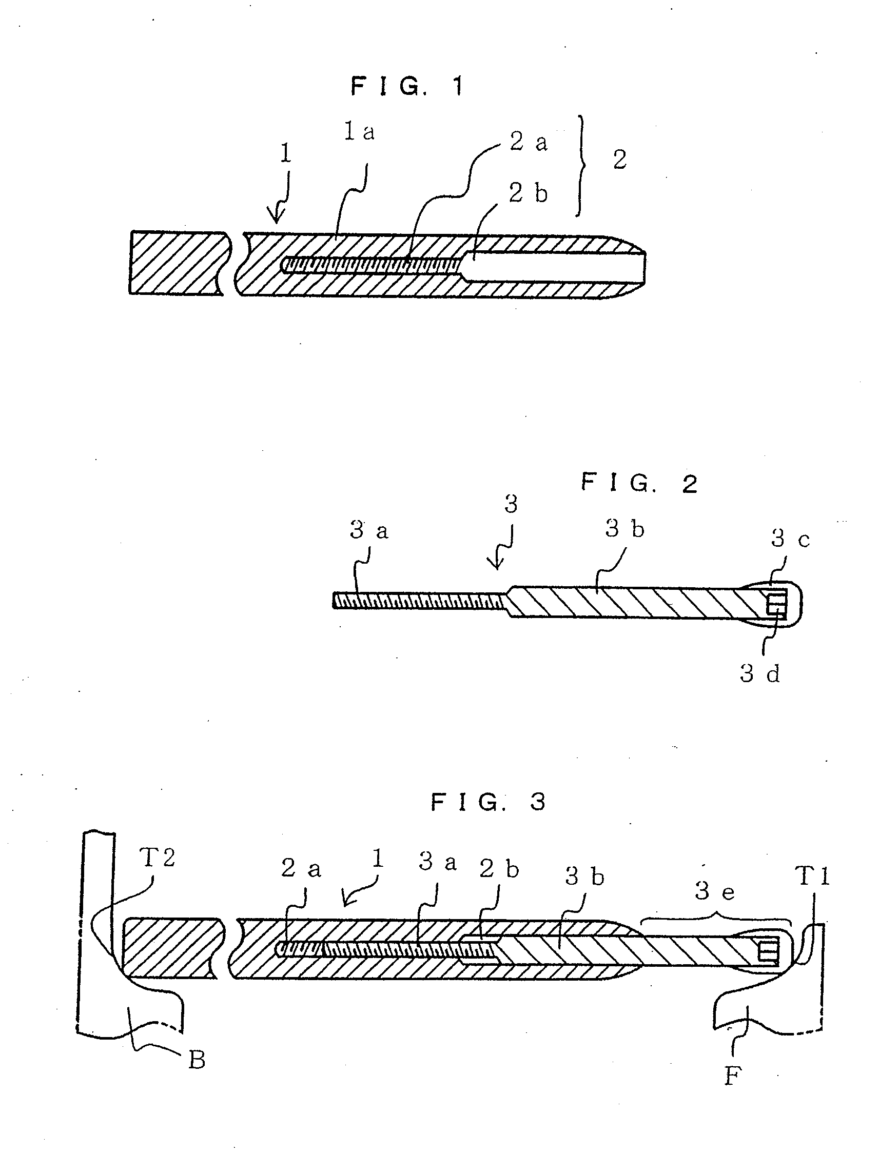
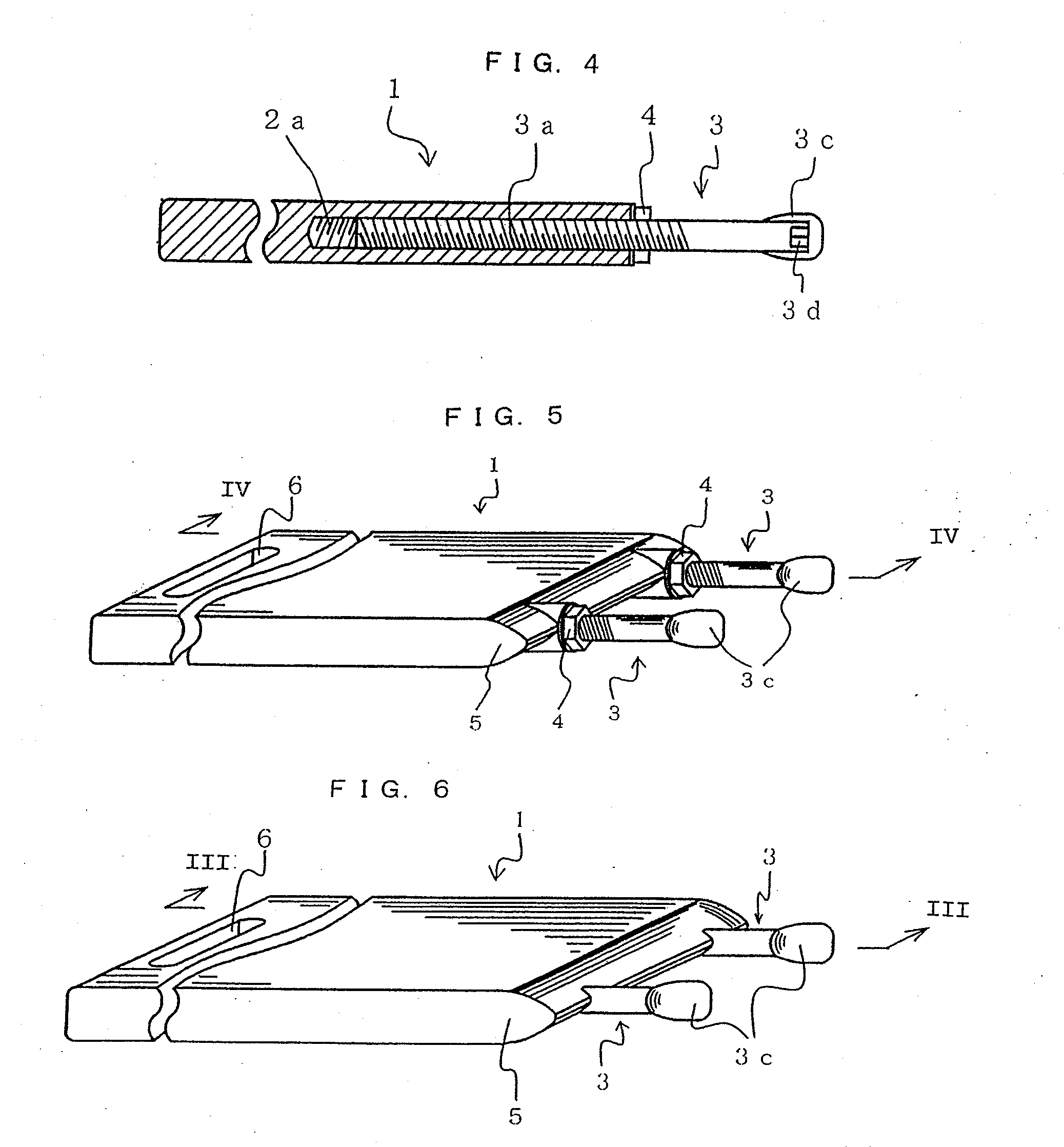
[0025]The best mode of an embodiment for carrying out the invention will be described below in detail with reference to the accompanying drawings. It should be appreciated that the invention is not limited to the embodiment described herein as well as any other embodiments. The cutting board of the invention according to the embodiment encompasses all the aforementioned first to fourth aspects of the invention and the cutting boards of the invention according to the other embodiments encompass the aforementioned second to fifth aspects of the invention. FIG. 1 is an end view illustrating a portion of a retaining hole of the cutting board according to the embodiment of the invention; FIG. 2 is a longitudinal sectional view of a projecting rod with a cap covering one end of the rod; and FIG. 3 is a cross-sectional view illustrating a state that the cutting board, having the projecting rod inserted into the retaining hole of the cutting board in order to secure it in the retaining hole...


PUM


Abstract

A cutting board, including retaining holes in a side surface thereof, each retaining hole including a screw hole at an end side of the retaining hole and a first fitting portion at an opening side of the retaining hole; projecting rods inserted into the retaining holes each include a cylindrical second fitting portion and a threaded portion to be screwed onto the screw hole with ends of the second fitting portion projecting from the side surface of the cutting board; a remaining portion of each first fitting portion is fit into the fitting portion of each retaining hole; each projecting rod is pivoted in a forward and reverse direction to allow the threaded portion thereof to move in a left and right direction within the screw hole; the length of each of the projecting portions projecting from the side surface of the cutting board is adjusted to fasten each projecting rod.

Description

REFERENCE TO RELATED APPLICATION[0001]This is a continuation application of Ser. No. 11 / 810,538, filed Jun. 6, 2007, which is currently pending. The subject matter of the aforementioned prior application is hereby incorporated herein by reference.BACKGROUND OF THE INVENTION[0002]The present invention relates to a cutting board intended to be used in such a way that it is placed on an upper section of a sink. More specifically, the invention relates to the cutting board excellent in a drainage function that includes projecting rods projecting from a side surface of the cutting board, a length of a projecting portion of each of the projecting rods being adjustable at will, which can be used for every shaped and every sized sink, and which can effectively drain water on the cutting board into an interior of a sink.[0003]There has been a cutting board intended to be used in such a way that it is set slidably in an upper section of a sink, for example, of a built-in kitchen. Since such a...

Claims


Application Information

Patent Timeline
Patent Type & Authority Applications(United States)
IPC IPC(8): A47J47/20
CPCA47J47/20A47J47/005
Inventor NISHIDA, KUNIHIKO
Owner NISHIDA KUNIHIKO
Learn More