Transmission device, transmission method, reception device, reception method, communication system, and communication method

a technology of transmission device and transmission method, which is applied in the direction of picture reproducers, picture reproducers using projection devices, instruments, etc., can solve the problems of spoiled beauty of advertisement and the like that is the information into difficult for the user to recognize the position at which the bar code is embedded and grasp the position, and difficult for a human to identify the light, etc., to achieve the effect of simple configuration

Active Publication Date: 2011-12-08
SONY CORP
View PDF12 Cites 119 Cited by
  • Summary
  • Abstract
  • Description
  • Claims
  • Application Information

AI Technical Summary

Benefits of technology

In light of the foregoing, it is desirable to provide a novel and improved technology which is capable of simply configuring a reception device, and which is capable of transmitting data from a transmission device to the reception device without spoiling the beauty of the surroundings.
According to the embodiments of the present disclosure described above, the reception device can be simply configured, and data can be transmitted from the transmission device to the reception device without spoiling the beauty of the surroundings.

Problems solved by technology

However, since the bar code is used by being embedded into information in a form that can be identified by the human eye, when the bar code has a size of a certain level or more, the beauty of the advertisement and the like that is the information into which the bar code is embedded is spoiled.
On the other hand, unless the bar code has a size of a certain level or more, it becomes difficult for the user to recognize a position at which the bar code is embedded and to grasp the position to be imaged.
This is mainly because, since the LED is a semiconductor device, the LED is capable of modulating the light emitted from the LED at such high speed that it is difficult for a human to identify the light, and is capable of transmitting data at high speed as an optical signal.

Method used


Image

  • Transmission device, transmission method, reception device, reception method, communication system, and communication method
  • Transmission device, transmission method, reception device, reception method, communication system, and communication method
  • Transmission device, transmission method, reception device, reception method, communication system, and communication method

Examples


embodiment

1. EMBODIMENT

[1-1. Outline of Communication System]

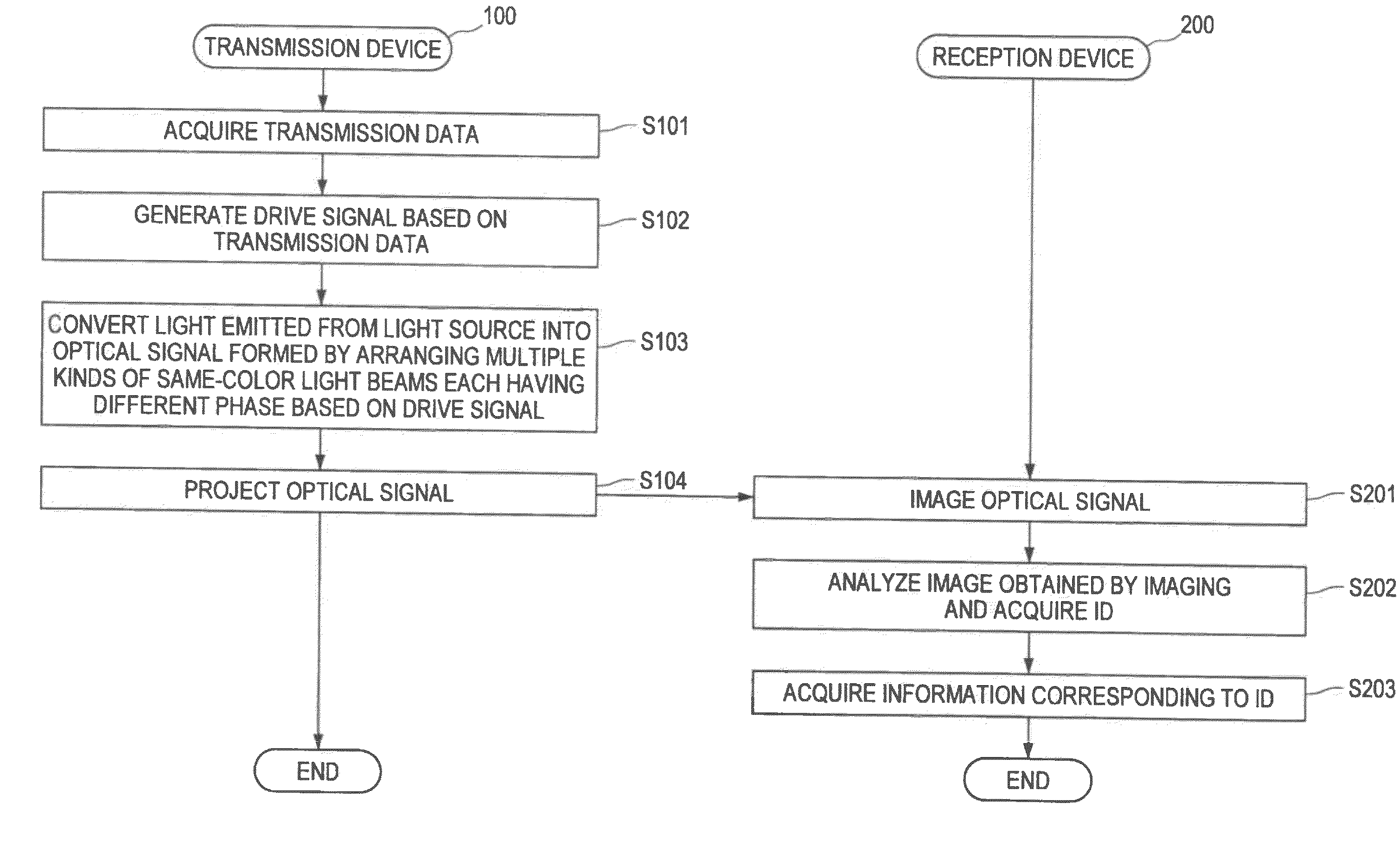
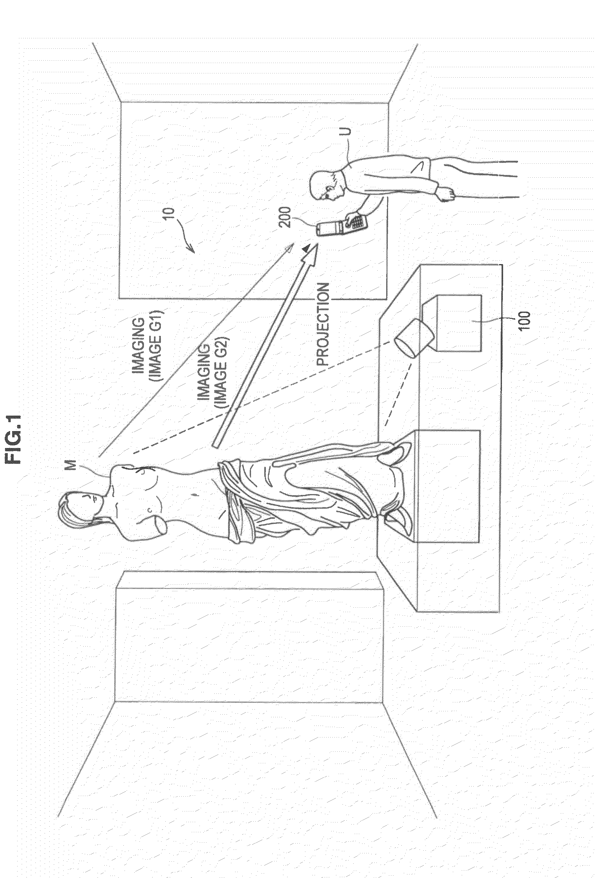
FIG. 1 is a diagram illustrating an outline of a communication system according to the present embodiment. First, with reference to FIG. 1, the outline of the communication system according to the present embodiment will be described. As shown in FIG. 1, a communication system 10 according to the present embodiment includes a transmission device 100 and a reception device 200. The transmission device 100 transmits data to be transmitted to the reception device 200 (hereinafter, also referred to as “transmission data”), and the reception device 200 receives the transmission data transmitted from the transmission device 100. In the present embodiment, although there will be described a case where the transmission device 100 transmits information on an art object M which is put on display in an art museum as transmission data and the reception device 200 receives the transmission data, the transmission data is not limited thereto.

Here,...


PUM


Abstract

There is provided a transmission device including an optical signal generation section configured to generate an optical signal formed by arranging one or more of each of a plurality of kinds of same-color light beams each having different phase, and a transmission section configured to transmit the optical signal generated by the optical signal generation section.

Description

BACKGROUNDThe present disclosure relates to a transmission device, a transmission method, a reception device, a reception method, a communication system, and a communication method.In recent years, there have been cases where, in digital signage and an advertisement, a bar code such as a QR code (registered trademark) is embedded into information shown to a user for attracting the user's attention to a website and the like. The bar code is embedded into the information in a form that a bit pattern obtained by encoding letters and numbers can be seen by the human eye. Accordingly, for example, when a position at which it is visually recognized by the user that the bit pattern is embedded is imaged by a camera provided to a mobile phone, and an image obtained as a result of the imaging is analyzed by the mobile phone, the bit pattern may be converted into a URL (Uniform Resource Locator) for specifying a website, a telephone number, and the like.According to such a technique, the user...

Claims


Application Information

Patent Timeline
Patent Type & Authority Applications(United States)
IPC IPC(8): H04B10/00H04B10/06H04B10/04H04M1/00G03B15/00H04B10/11H04J14/08H04N9/31
CPCG03B21/26H04B10/116H04B10/1149
Inventor REKIMOTO, JUNICHI
Owner SONY CORP
Why Eureka
Try Eureka