Reducing resonant currents in a resonating circuit during MRI scans

a resonating circuit and resonant current technology, applied in the field of implantable medical leads, can solve the problems of deteriorating stimulation thresholds, prone to heating and induced current, and existing implantable medical devices

Inactive Publication Date: 2011-12-08
PACESETTER INC
View PDF7 Cites 7 Cited by
  • Summary
  • Abstract
  • Description
  • Claims
  • Application Information

AI Technical Summary

Problems solved by technology

Existing implantable medical leads for use with implantable pulse generators, such as neurostimulators, pacemakers, defibrillators or implantable cardioverter defibrillators (“ICD”), are prone to heating and induced current when placed in the strong magnetic (static, gradient and RF) fields of a magnetic r...

Method used


Image

  • Reducing resonant currents in a resonating circuit during MRI scans
  • Reducing resonant currents in a resonating circuit during MRI scans
  • Reducing resonant currents in a resonating circuit during MRI scans

Examples


Embodiment Construction

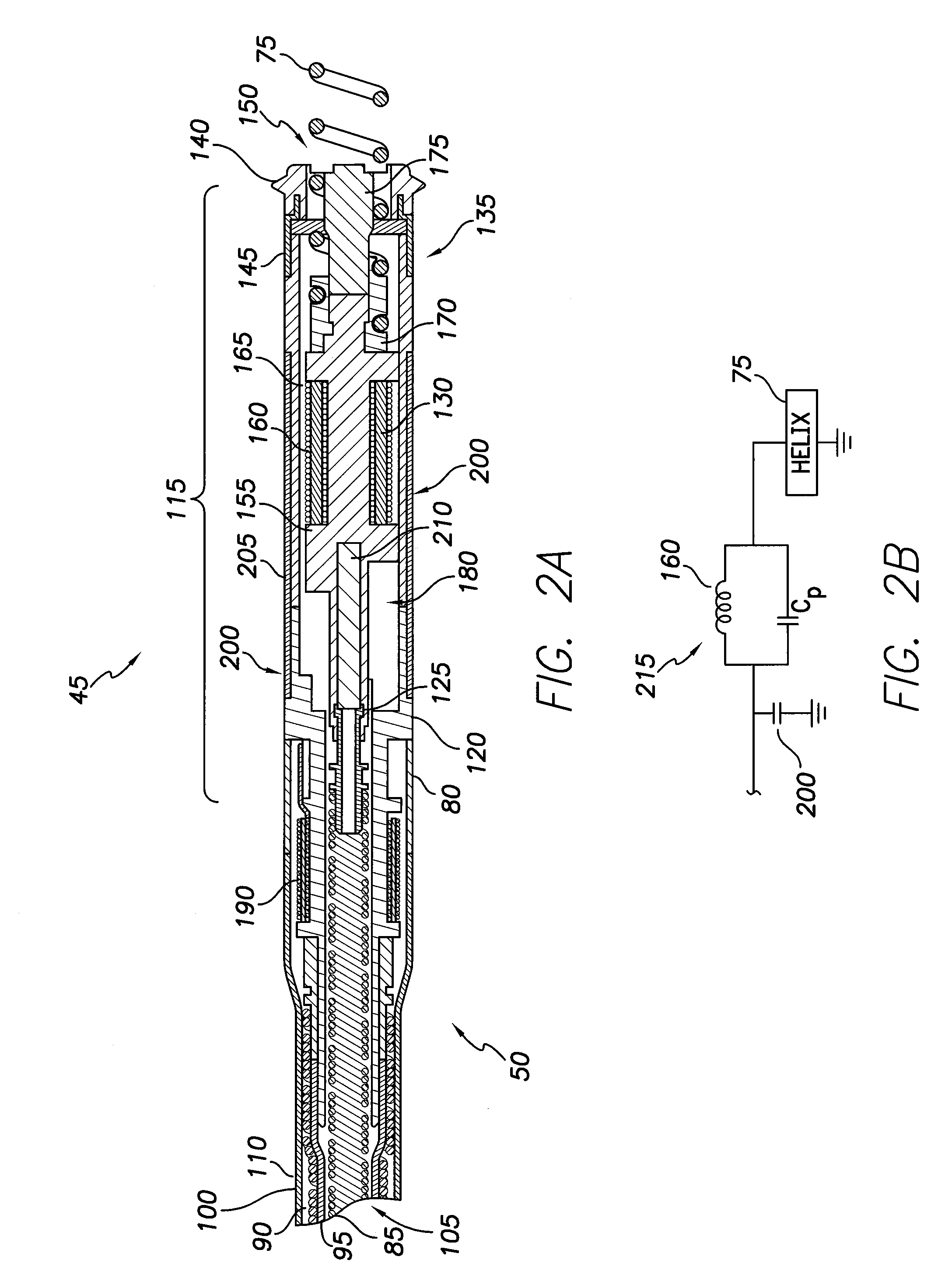
[0016]Supplying a RF resonant circuit, such as a LC tank circuit, at the distal end of a lead has shown great RF heating reduction independent of lead configuration, lead length and termination conditions. However, recent in-vitro tests also confirmed that due to resonant current at RF frequencies and series resistance, heating of a self-resonant inductor measured at the lead distal end header can be significant in gel (about 19 TC). Component heating in implantable medical leads is due to dissipated power. Power dissipation is represented as P=I2R, where I is electrical resonant current and R is the series resistance at the resonant frequency. Reducing I or R or both can, therefore, reduce heating. Additionally, electrical modeling shows that input current at the resonant circuit is proportional to the resonant current I, therefore, lowering input current at the LC tank is helpful to reduce component heating.

[0017]Disclosed herein is an implantable medical lead employing a lead str...


PUM

PropertyMeasurementUnit
Frequencyaaaaaaaaaa
Frequencyaaaaaaaaaa
Capacitanceaaaaaaaaaa

Abstract

An implantable medical lead configured to reduce resonant currents in a resonating circuit during MRI scans and a method of manufacturing the same are disclosed herein. The method of manufacturing includes providing a medical lead comprising an electrical pathway from a tip electrode located at a distal end of the lead to a lead connector located at a proximal end and coupling a resonating circuit to the tip electrode such that the resonating circuit is in the electrical pathway for the tip electrode. Further, the method includes coupling a capacitive element to a proximal end of the resonating circuit. The capacitive element is configured to shunt at least part of an RF current induced on the electrical pathway into surrounding tissue or fluid and also works as a heat sink to spread the heat from the internal LC resonant circuit.

Description

FIELD OF THE INVENTION[0001]The present invention relates to implantable medical leads. More specifically, the present invention relates to implantable medical leads having a lead structure based capacitor to reduce heating.BACKGROUND OF THE INVENTION[0002]Existing implantable medical leads for use with implantable pulse generators, such as neurostimulators, pacemakers, defibrillators or implantable cardioverter defibrillators (“ICD”), are prone to heating and induced current when placed in the strong magnetic (static, gradient and RF) fields of a magnetic resonance imaging (“MRI”) machine. The heating and induced current are the result of the lead acting like an antenna in the magnetic fields generated during a MRI. Heating and induced current in the lead may result in deterioration of stimulation thresholds or, in the context of a cardiac lead, even increase the risk of cardiac tissue damage and perforation.[0003]Over fifty percent of patients with an implantable pulse generator a...

Claims


Application Information

Patent Timeline
IPC IPC(8): A61N1/05H01R43/20
CPCA61N1/0573Y10T29/49208A61N2001/086A61N1/086
Inventor ZHANG, JINMIN, XIAOYIVIOHL, INGMARMOUCHAWAR, GABRIEL A.CHEN, XIANGQUN
Owner PACESETTER INC
Why Eureka
Try Eureka