Eureka AIR delivers breakthrough ideas for toughest innovation challenges, trusted by R&D personnel around the world.

Method of manufacturing stator

Inactive Publication Date: 2011-12-15
AISIN AW CO LTD
View PDF7 Cites 11 Cited by
  • Summary
  • Abstract
  • Description
  • Claims
  • Application Information

AI Technical Summary

Benefits of technology

[0009]The present invention has been devised in consideration of the foregoing problem with related art, and it is an object of the present invention to provide a method of manufacturing a stator that is capable of effectively suppressing a reduction in the circularity of the stator after a heated outer peripheral ring is fit to an outer periphery of a plurality of segment cores.
[0010]A first aspect of the present invention provides a method of manufacturing a stator, the method being characterized by including: a stator formation process of forming a stator by assembling a plurality of segment cores, which is formed by dividing a stator core in a circumferential direction at a formation position of a slot of the stator core, to a coil conductor that is formed of a rectangular wire bent to include linear portions arranged in the slot and bridge portions that alternately connects the linear portions on one end and the other end of the coil conductor such that the linear portions can be arranged side by side on an imaginary circumference, and fitting a heated outer peripheral ring to an outer periphery of the plurality of segment cores; and a correction process of reheating the stator at a predetermined temperature in a state where a circularity of the stator is corrected by restraining the outer peripheral ring in the stator so as to improve the circularity of the stator.
[0013]This reheating makes it possible to reduce a force that causes the coil conductor deformed when arranged in the slots to regain its original shape. Consequently, it is possible to suppress the force that causes the deformed coil conductor to regain its original shape from serving as a residual stress that presses and expands the segment cores.
[0014]Therefore, according to the method of manufacturing a stator of the first aspect of the present invention, it is possible to effectively suppress a reduction in the circularity of the stator after the heated outer peripheral ring is fit to the outer periphery of the plurality of segment cores.

Problems solved by technology

That is, a dimensional error may occur between the slots and the coil conductor due to, for example, a variation in dimensional accuracy that occurs when the rectangular wire is processed by bending.
This results in considerable deformation of the coil conductor arranged in the slots.

Method used


Image

  • Method of manufacturing stator
  • Method of manufacturing stator
  • Method of manufacturing stator

Examples


embodiment

[0043]An embodiment of a method of manufacturing a stator according to the present invention will be hereinafter described with reference to the drawings.

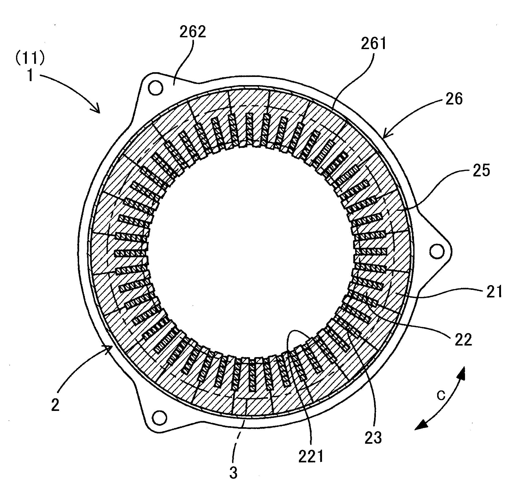
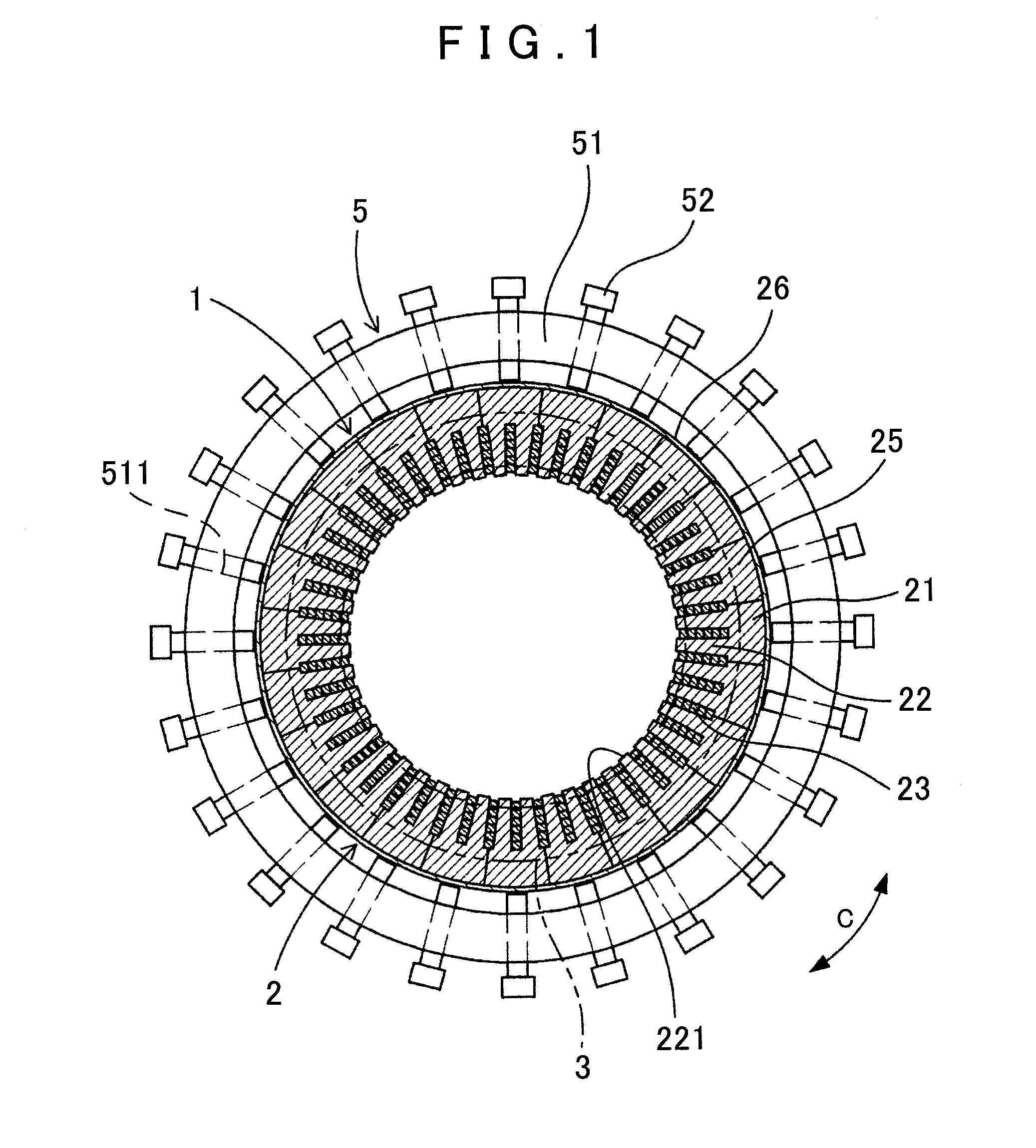
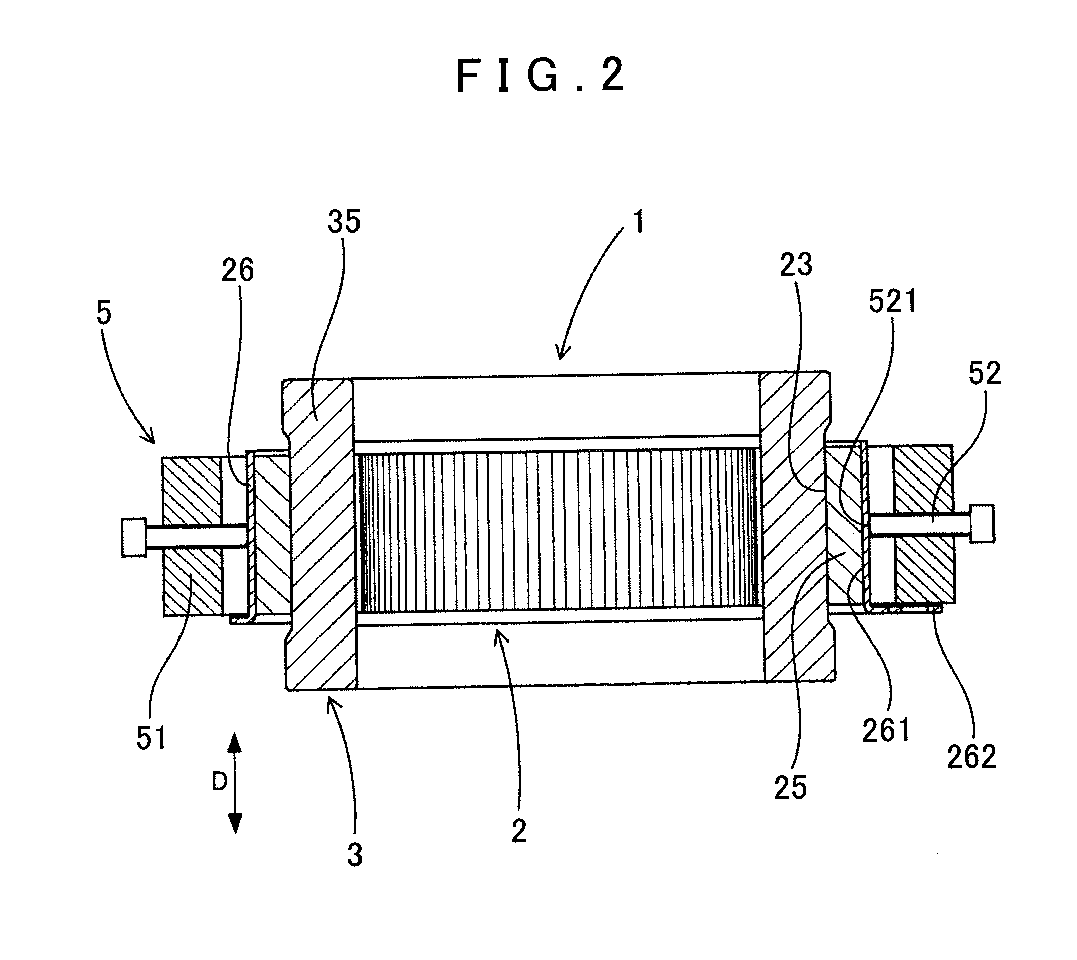
[0044]In a method of manufacturing a stator 1 according to the present embodiment, the stator 1 for a rotary electric machine is manufactured by performing a stator formation process and a correction process to be described next.

[0045]In the stator formation process, as shown in FIGS. 3 and 9, a rectangular wire 301 whose cross-section is generally rectangular-shaped is processed by bending so as to form a coil conductor 3. The coil conductor 3 includes linear portions 31 to be respectively arranged in a plurality of slots 23 of a stator core 2, and bridge portions 32 that alternately connect the linear portions 31 on one end and the other end of the coil conductor 3 so as to arrange the linear portions 31 side by side on an imaginary circumference. Next, as shown in FIG. 4, a plurality of segment cores 25 is formed by dividing the...


PUM

PropertyMeasurementUnit
Temperatureaaaaaaaaaa
Radiusaaaaaaaaaa
Circumferenceaaaaaaaaaa

Abstract

A method of manufacturing a stator includes forming a stator by assembling segment cores, formed by dividing a stator core in a circumferential direction at a formation position of a slot of the stator core, to a coil conductor that is formed of a rectangular wire bent to include linear portions arranged in the slot and bridge portions that alternately connect the linear portions on one end and the other end of the coil conductor such that the linear portions can be arranged side by side on an imaginary circumference, and fitting a heated outer peripheral ring to an outer periphery of the segment cores. The method also includes reheating the stator at a predetermined temperature in a state where a circularity of the stator is corrected by restraining the outer peripheral ring in the stator to improve the circularity of the stator.

Description

INCORPORATION BY REFERENCE[0001]The disclosure of Japanese Patent Application No. 2010-136034 filed on Jun. 15, 2010 including the specification, drawings and abstract is incorporated herein by reference in its entirety.BACKGROUND OF THE INVENTION[0002]The present invention relates to a method of manufacturing a stator in which a coil conductor is arranged in slots of a stator core.DESCRIPTION OF THE RELATED ART[0003]To manufacture a stator for a rotary electric machine that is used in a hybrid vehicle, an electric vehicle, or the like, a coil conductor is formed of a rectangular wire whose cross-section is generally rectangular-shaped in order to increase the area of the slot of a stator core occupied by the coil conductor. In this case, the coil conductor formed of the rectangular wire cannot be inserted into the slots in the annular stator core. A plurality of segment cores is thus formed by dividing the stator core at a formation position of every other slot.[0004]The plurality ...

Claims


Application Information

Patent Timeline
IPC IPC(8): H02K15/02
CPCH02K15/024H02K15/028Y10T29/49009H02K15/12H02K15/066
Inventor SAITO, MASAKISHIMIZU, SHINYAKATO, SUSUMU
Owner AISIN AW CO LTD
Why Eureka
Eureka Blog
Learn More