Apparatus for separating particles and methods for using same

a technology of apparatus and particles, applied in the field of apparatus for separating particles, can solve the problems of not teaching or performing the function of apparatus to separate particles traveling through them and the apparatus fails to separate particles into two or more groups

Active Publication Date: 2011-12-15
THE PROCTER & GAMBLE COMPANY
View PDF2 Cites 17 Cited by
  • Summary
  • Abstract
  • Description
  • Claims
  • Application Information

AI Technical Summary

Benefits of technology

[0008]The present invention fulfills the need described above by providing an apparatus capable of separat

Problems solved by technology

However, upon closer inspection and modeling, the apparatus fails to separate particles into two or more groups as they are traveling through the apparatus.
As a result of the designs of the prior art apparatuses, none of them teach or function

Method used


Image

  • Apparatus for separating particles and methods for using same
  • Apparatus for separating particles and methods for using same
  • Apparatus for separating particles and methods for using same

Examples


Embodiment Construction

Definitions

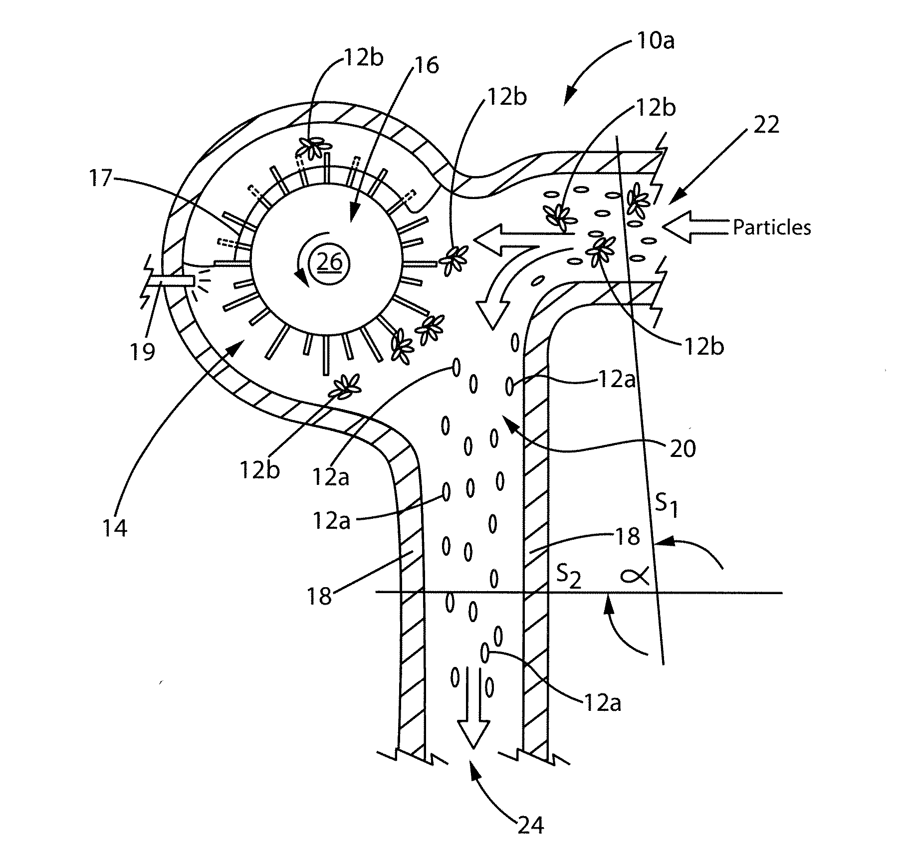
[0038]“Separator component” as used herein means a portion of an apparatus for separating particles, which is capable of diverting a portion (less than all) of the particles traveling through the apparatus such that the diverted particles are separated from the other particles that continue to travel through the apparatus. The separator component is that portion of the apparatus between an imaginary surface S1 normal to the inlet of the apparatus and an imaginary surface S2 normal to the outlet of the apparatus, as shown in FIG. 6. The angle at which the imaginary surfaces S1 and S2 intersect is angle α. The separator component may use inertial and / or aerodynamic characteristic differences between the particles traveling through the apparatus to facilitate the separation of the particles into two or more distinct groups.

[0039]The separator component may comprise an active component, such as a rotating pinwheel that the diverted particles contact. The separator component m...


PUM

PropertyMeasurementUnit
Angleaaaaaaaaaa
Angleaaaaaaaaaa
Angleaaaaaaaaaa

Abstract

An apparatus suitable for separating particles and methods for using such apparatus are provided.

Description

CROSS REFERENCE TO RELATED APPLICATION(S)[0001]This application claims the benefit of U.S. Provisional Application No. 61 / 352,989 filed Jun. 9, 2010.FIELD OF THE INVENTION[0002]The present invention relates to an apparatus suitable for separating particles and methods for using such apparatus. More particularly, the present invention relates to an apparatus that utilizes inertial and / or aerodynamic characteristic (for example drag) differences in particles to separate particles into two or more groups.BACKGROUND OF THE INVENTION[0003]Apparatuses for conveying particles, such as pulp fibers are known in the art. For example, there are numerous air-laying forming heads that utilize pinwheels and / or screens and / or sieves through which all of the particles traveling through the apparatuses pass. These known apparatuses do not separate a portion of the particles from the other particles as the particles are traveling through the apparatuses. As can be seen in FIGS. 1-4, the prior art app...

Claims


Application Information

Patent Timeline
IPC IPC(8): B07B7/00B27N3/04D21H11/00
CPCB07B7/01B07B7/08D01G5/00B29C70/06D04H1/732D04H1/736B07B7/00D04H1/72Y10T442/60
Inventor YOUNG, CHRISTOPHER MICHAELEROGLU, HASANMCKIBBEN, JOHN FERNEYBARNHOLTZ, STEVEN LEE
Owner THE PROCTER & GAMBLE COMPANY
Why Eureka
Try Eureka