Ac power supply for sputtering apparatus

a technology of ac power supply and sputtering machine, which is applied in the direction of dc-ac conversion without reversal, process and machine control, instruments, etc., can solve the problems of inability to efficiently suppress current rise, inducing arc discharge, and good films cannot be formed, so as to prevent induction of arc discharge

Active Publication Date: 2011-12-15
ULVAC INC
View PDF5 Cites 9 Cited by
  • Summary
  • Abstract
  • Description
  • Claims
  • Application Information

AI Technical Summary

Benefits of technology

[0008]In view of the points described above, it is an object of the present invention to provide an AC power supply for a sputtering apparatus in which the AC power supply is capable of preventing induction of an arc discharge by suppressing an overvoltage generated at the time of reversing the polarity of each electrode.

Problems solved by technology

That is, particles and splashes (each being a lump having a diameter of several μm to several hundred μm) are generated, and good films cannot be formed.
As a result, a current rise cannot efficiently be suppressed, and there is a problem in that an overcurrent flows in a short time (in several μs) (that is, a current rise rate per unit time at the time of generation of an arc discharge is high).
There is thus a fear that such an overvoltage induces an arc discharge.

Method used


Image

  • Ac power supply for sputtering apparatus
  • Ac power supply for sputtering apparatus
  • Ac power supply for sputtering apparatus

Examples


first embodiment

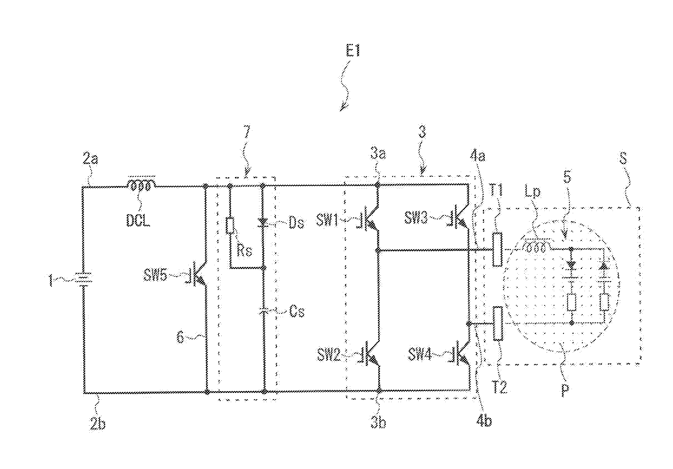
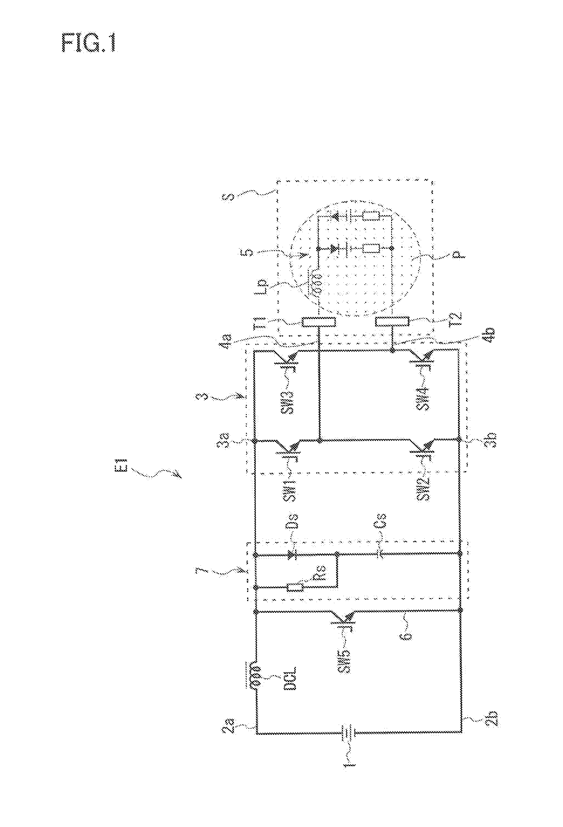
[0025]With reference to FIG. 1, the configuration of an AC power supply E1 according to the present invention will be described. The AC power supply E1 is an AC pulsed power supply arranged to lie opposite to a to-be-processed substrate, e.g., in a sputtering apparatus S. The AC pulsed power supply is used to supply bipolar pulsed electric power at a predetermined frequency to a couple of targets T1 and T2, these targets being electrodes contacting a plasma load P. Here, the plasma load P can be expressed by an equivalent circuit 5. The equivalent circuit 5 includes an inductance component Lp having an inductance value of 20 μH to 30 μH and is capacitively coupled with the couple of targets T1 and T2.

[0026]The AC power supply E1 includes a DC electric power supply source 1, which is made up of an DC power source outputting, e.g., a DC voltage of 500 V. A bridge circuit 3 made up of four switching transistors SW1-SW4 is provided between positive and negative output lines 2a and 2b fr...

second embodiment

[0041]Next, with reference to FIG. 4, the configuration of the AC power supply E2 of a second embodiment will be described. In the AC power supply E2, the connection position of one end of the snubber resistor Rs constituting the snubber circuit 7 is different from that of the AC power supply E1 described above. That is, one end of the snubber resistor Rs is connected to a point between the DC electric power supply source 1 and the inductor DCL. The other end of the snubber resistor Rs is connected to a point between the cathode of the snubber diode Ds and the snubber capacitor Cs in a manner similar to the arrangement in the AC power supply E1. The other configurations of the AC power supply E2 and the switching control of the switching transistors SW1-SW4 and the short-circuiting switching transistor SW5 are similar to those of the AC power supply E1, and their detailed descriptions are accordingly omitted.

[0042]According to the AC power supply E2 of the present embodiment, if the...


PUM

PropertyMeasurementUnit
diameteraaaaaaaaaa
inductanceaaaaaaaaaa
DC voltageaaaaaaaaaa

Abstract

There is provided an AC power supply for a sputtering apparatus in which the AC power supply can prevent the induction of an arc discharge by suppressing an overvoltage to be generated when the polarity of each electrode is reversed. A bridge circuit made up of a plurality of switching transistors SW1-SW4 is disposed between positive and negative DC current output lines from a DC electric power supply source. An inductor DCL which makes a DC output to have a constant-current characteristic is disposed in at least one of the positive and the negative DC output lines from the DC electric power supply source to the bridge circuit, and a snubber circuit is disposed in parallel with inputs of the bridge circuit.

Description

TECHNICAL FIELD[0001]The present invention relates to an AC power supply for a sputtering apparatus, the AC power supply being for supplying bipolar pulsed electric power to the sputtering apparatus.BACKGROUND ART[0002]An AC power supply to supply bipolar pulsed electric power is used, e.g., for a sputtering apparatus which forms a predetermined thin film on a surface of a substrate to be processed (hereinafter referred to as “a to-be-processed substrate”). As an AC power supply of this type, there is known one including a bridge circuit made up of four switching elements (MOSFETs) disposed between a DC electric power supply source and a load. When each of the switching elements of the bridge circuit is appropriately operated to apply an arbitrary pulsed voltage to a couple of targets, which are output terminals (electrodes), with the polarity of the pulsed voltage alternately reversed at a predetermined frequency, then the polarity of each of the targets is alternately switched bet...

Claims


Application Information

Patent Timeline
Patent Type & Authority Applications(United States)
IPC IPC(8): H02M7/42C23C14/34
CPCC23C14/3464H01J37/34H01J37/3444C23C14/3485H02M7/53871H02M2001/344H01J37/3467H02M1/34H02M1/344C23C14/34G05F3/04H02M7/5387
Inventor YANAGIYA, YOSHIO
Owner ULVAC INC
Why Eureka
Try Eureka