Power storage device
a technology of power storage and discharge capacity, which is applied in the direction of cell components, final product manufacturing, sustainable manufacturing/processing, etc., can solve the problems of deterioration of the charge-discharge cycle characteristics of the power storage device, and achieve the reduction of resistance between the current collector and the active material layer or between the metal layer and the active material layer
- Summary
- Abstract
- Description
- Claims
- Application Information
AI Technical Summary
Benefits of technology
Problems solved by technology
Method used
Image

Examples
embodiment 1
[0028]In Embodiment 1, according to one embodiment of the present invention, an electrode for a power storage device and a method for manufacturing the electrode will be described using FIGS. 1A and 1B, 2A and 2B, and 3A and 3B, and FIG. 4.
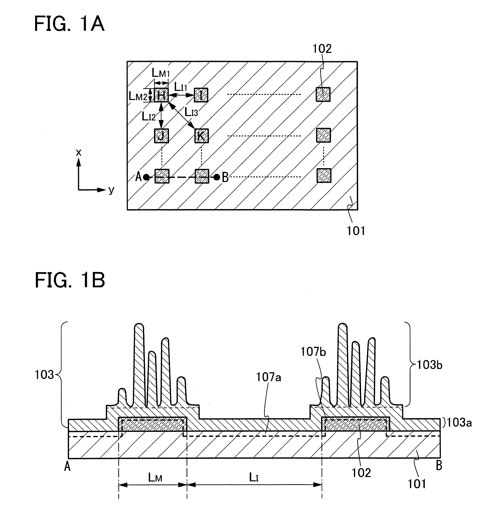
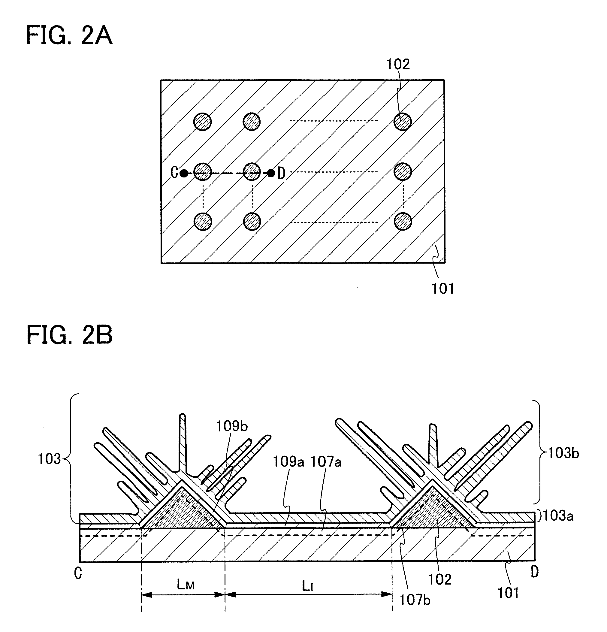
[0029]FIG. 1A is one example of a top view of an electrode for a power storage device, and FIG. 1B is a cross-sectional view along line A-B in FIG. 1A. An active material layer 103 is omitted in FIG. 1A.
[0030]The electrode for a power storage device shown in FIGS. 1A and 1B is manufactured as follows: a metal layer is formed over a current collector 101 and is selectively etched to form a plurality of metal layers 102; and a crystalline silicon layer is formed as the active material layer 103 over the current collector 101 and the metal layers 102 by a thermal CVD (Chemical Vapor Deposition) method, preferably a Low Pressure Chemical Vapor Deposition (LPCVD) method.
[0031]In the electrode shown in FIGS. 1A and 1B, the metal layers 102 are disposed ...
embodiment 2
[0072]In Embodiment 2, a structure of a power storage device will be described with reference to FIGS. 5A and 5B.
[0073]First, a structure of a secondary battery which is one example of a power storage device is described. Among secondary batteries, a lithium-ion battery using a metal oxide containing lithium, such as LiCoO2, has a large discharge capacity and high safety. In this embodiment, a structure of a lithium-ion battery that is a typical example of a secondary battery is described.
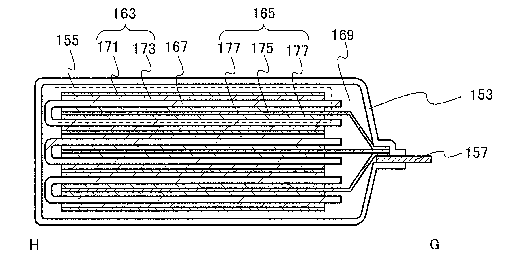
[0074]FIG. 5A is a plan view of a power storage device 151, and FIG. 5B is a cross-sectional view along line G-H in FIG. 5A.
[0075]The power storage device 151 illustrated in FIG. 5A includes a power storage cell 155 in an exterior member 153. Terminal portions 157 and 159 which are connected to the power storage cell 155 are also provided. For the exterior member 153, a laminate film, a polymer film, a metal film, a metal case, a plastic case, or the like can be used.
[0076]As illustrated in FIG. 5B...
embodiment 3
[0095]In Embodiment 3, an application embodiment of the power storage device described in Embodiment 2 is described with reference to FIG. 6.
[0096]The power storage device described in Embodiment 2 can be used in electronic devices, e.g., cameras such as digital cameras or video cameras, digital photo frames, mobile phones (also referred to as cellular phones or cellular phone devices), portable game machines, portable information terminals, or audio reproducing devices. Further, the power storage device can be used in electric propulsion vehicles such as electric vehicles, hybrid electric vehicles, train vehicles, maintenance vehicles, carts, or wheelchairs. Here, as a typical example of the electric propulsion vehicles, a wheelchair is described below.
[0097]FIG. 6 is a perspective view of an electric wheelchair 501. The electric wheelchair 501 includes a seat 503 where a user sits down, a backrest 505 provided behind the seat 503, a footrest 507 provided at the front of and below ...
PUM
 Abstract
Description
Claims
Application Information
 - R&D Engineer
- R&D Manager
- IP Professional
- Industry Leading Data Capabilities
- Powerful AI technology
- Patent DNA Extraction
Browse by: Latest US Patents, China's latest patents, Technical Efficacy Thesaurus, Application Domain, Technology Topic.
© 2024 PatSnap. All rights reserved.Legal|Privacy policy|Modern Slavery Act Transparency Statement|Sitemap