Connector with a laterally moving contact

a connector and contact technology, applied in the direction of coupling contact members, coupling device connections, securing/insulating coupling contact members, etc., can solve the problems of insufficient space to laterally move the connectors relative to each other, affecting the coupling between the connector and the contact pad, and affecting the coupling between the contact pad and the layer

Inactive Publication Date: 2011-12-15
TE CONNECTIVITY CORP
View PDF38 Cites 34 Cited by
  • Summary
  • Abstract
  • Description
  • Claims
  • Application Information

AI Technical Summary

Problems solved by technology

The layer may negatively impact the coupling between the connector and the contact pads.
In some applications, there is insufficient room to laterally move the connector

Method used


Image

  • Connector with a laterally moving contact
  • Connector with a laterally moving contact
  • Connector with a laterally moving contact

Examples


Embodiment Construction

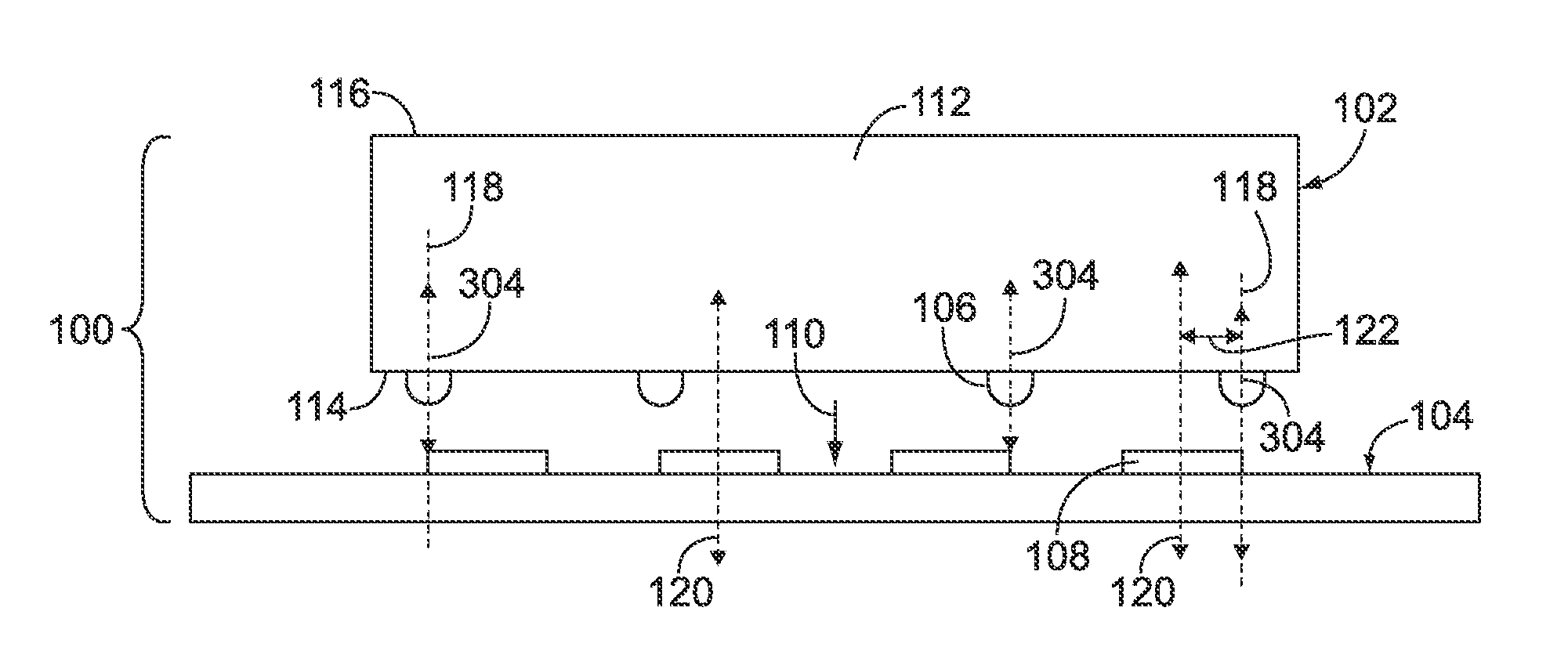
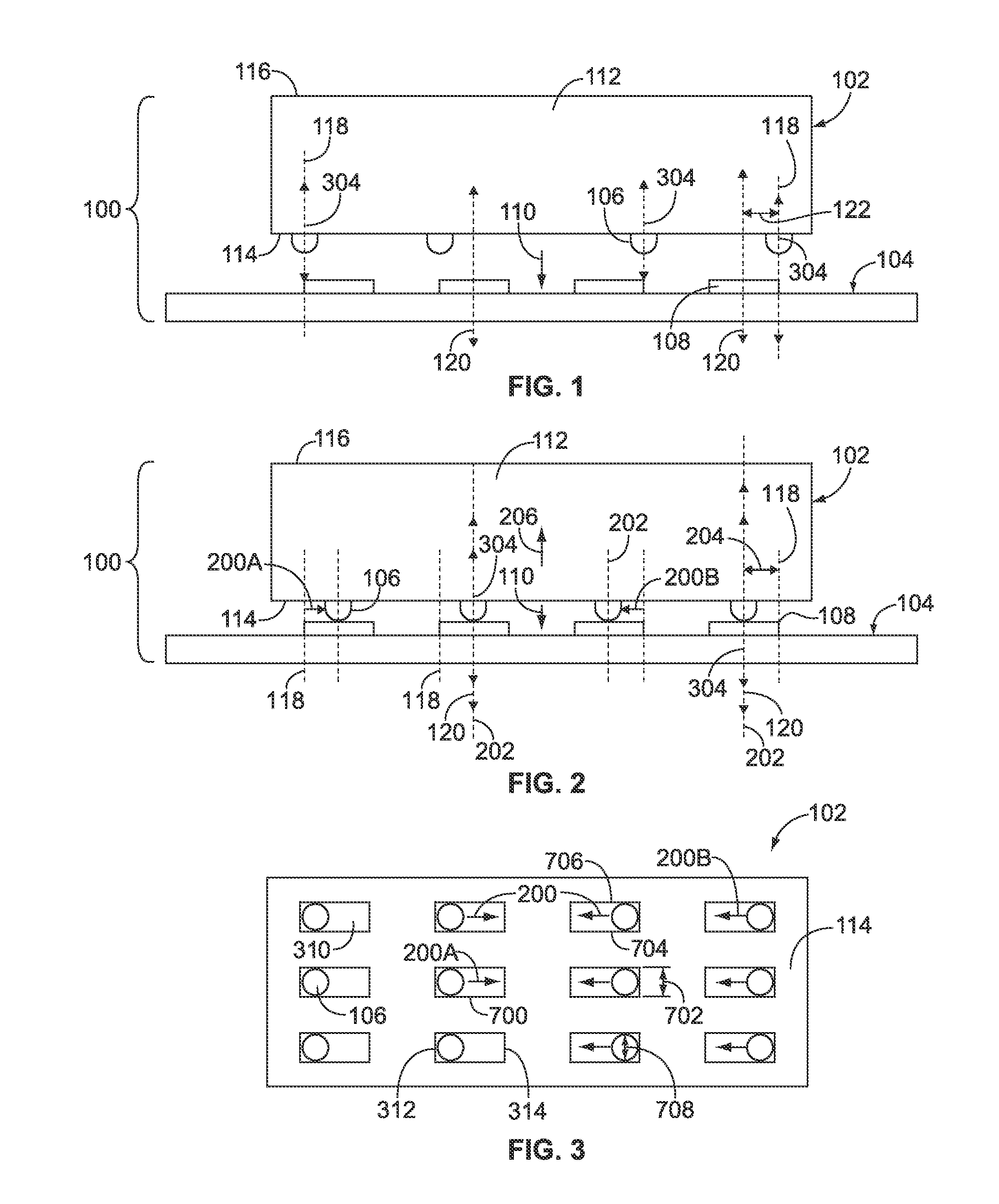
[0038]FIG. 1 is an elevational view of a decoupled connector system 100 in accordance with one embodiment of the present disclosure. FIG. 2 is an elevational view of a coupled or mated connector system 100 in accordance with one embodiment of the present disclosure. The system 100 includes two connectors 102, 104 that mate with one another to communicate data signals and / or electric power between the connectors 102, 104. The connector 104 may be referred to herein as a mating connector. The first connector 102 includes a housing 112 that extends from a front end 114 to a back end 116. Several contacts 106 are disposed within the housing 112 and protrude from the front end 114. Alternatively, the contacts 106 may be recessed within the housing 112 such that the contacts 106 do not protrude from the front end 114. The number of contacts 106 shown in FIGS. 1 and 2 is provided merely as an example.

[0039]The contacts 106 engage corresponding conductive elements 108 of the second connecto...


PUM


Abstract

A connector includes a housing, a contact, an angled interface, and a resilient member. The contact is disposed in the housing and includes a mating end and an interface end. The angled interface includes a sliding surface that is oriented at an oblique angle with respect to the longitudinal axis. The resilient member is coupled with the contact and the housing and is configured to apply a force to the contact in a direction that is angled with respect to the longitudinal axis. The mating end of the contact engages a conductive element of a mating connector and the interface end of the contact slides along the sliding surface of the angled interface when the contact is moved in a mating direction toward the conductive element. The angled interface translates movement of the contact in the mating direction into lateral movement across the conductive element.

Description

BACKGROUND OF THE INVENTION[0001]The subject matter herein relates generally to electrical connectors and, more particularly, to connectors that include contacts that mate with one another.[0002]Known connectors include contacts disposed within or coupled with a housing. The housings mate with one another to electrically couple the contacts. Once the contacts are joined with one another, the connectors communicate data signals and / or power between each other via the coupled contacts. Some known connectors include contacts that mate with contact pads of another connector. For example, a connector system may include a first connector that includes several contacts while a second connector includes several substantially flat contact pads. By way of example only, the second connector may be a printed circuit board that includes contact pads disposed on one side of the board. The contacts engage the contact pads to electrically couple the contacts with the contact pads.[0003]The contact ...

Claims


Application Information

Patent Timeline
IPC IPC(8): H01R13/40
CPCH01R12/91H01R13/6315H01R13/2407H01R13/2421
Inventor MULFINGER, ROBERT NEILHAMNER, RICHARD ELOF
Owner TE CONNECTIVITY CORP
Why Eureka
Try Eureka