Body position and pressure control apparatus

a pressure control apparatus and body position technology, applied in the field of body position and pressure control apparatus, can solve the problems of increasing the number of electrodes and wirings, complicating the apparatus configuration, and reducing so as to improve the comfort of sleepers, the ability of the body of the sleeper is further improved, and the sense of discomfort of the sleeper is further reduced

Active Publication Date: 2011-12-22
SUMITOMO RIKO CO LTD
View PDF0 Cites 53 Cited by
  • Summary
  • Abstract
  • Description
  • Claims
  • Application Information

AI Technical Summary

Benefits of technology

[0040]In this configuration, the front electrodes and the rear electrodes can expand and contract along with the sensor thin film. Thus, it is unlikely that the front electrodes and the rear electrodes prevent the sensor thin film from expanding and contracting. Furthermore, the stretchability of the sensor main body further increases as a whole. Thus, the following capability to the body of the sleeper is further improved and a sense of discomfort of the sleeper is further reduced. The durability of the sensor main body is also improved.

Problems solved by technology

Each pressure sensor requires electrodes and wirings, thus inevitably increasing the number of electrodes and wirings and complicating the apparatus configuration.
Furthermore, a sensor sheet including the pressure sensors is not soft and has poor stretchability.
Thus, the sensor sheet placed on an upper surface of the mattress is difficult to fit along a body of a sleeper, thus causing a sense of discomfort for the sleeper.
In the case where the body position is changed, the sensor sheet is difficult to follow the body movement.
In addition, the sensor sheet is difficult to follow the movement of inflation and deflation of the air bags, thus deteriorating the detection accuracy of body pressure distribution.
It is thus difficult to reduce the pressure exerted on a bone projection portion, and accordingly a bedsore prevention effect is not sufficient.

Method used


Image

  • Body position and pressure control apparatus
  • Body position and pressure control apparatus
  • Body position and pressure control apparatus

Examples


first embodiment

[0069][Configuration of Body position and pressure Control Apparatus]

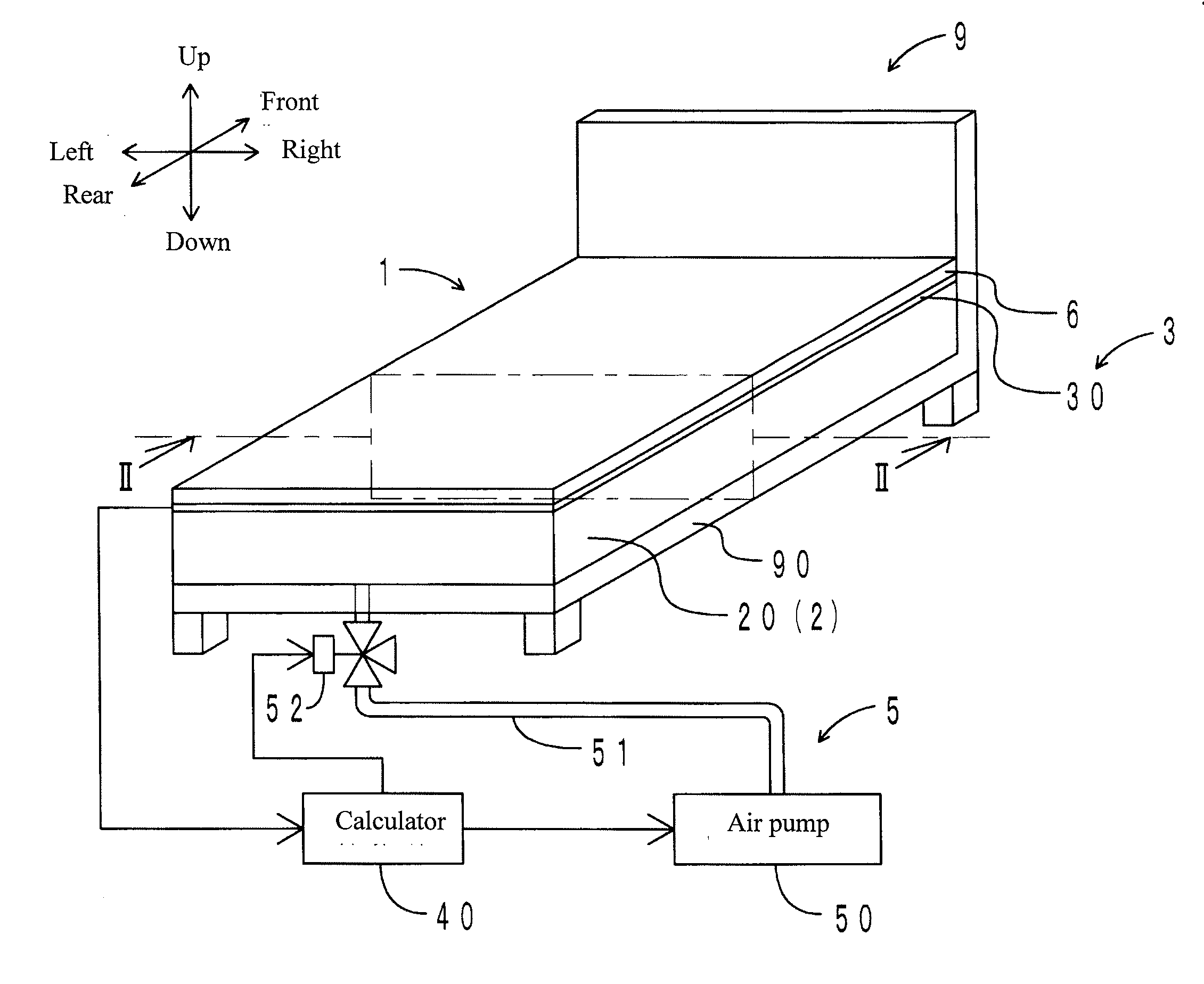
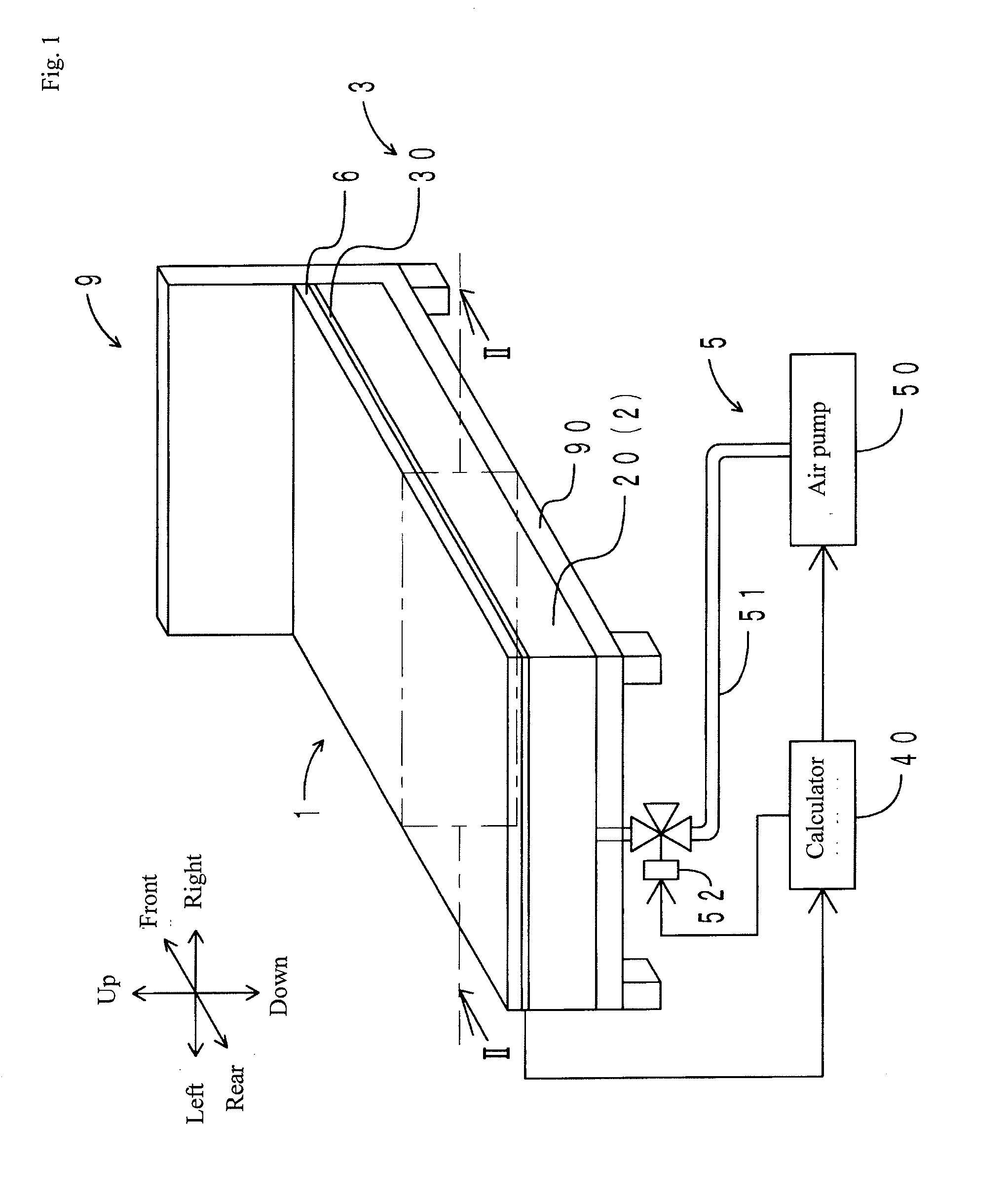
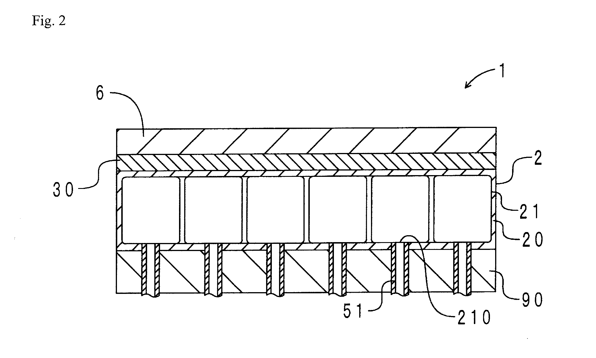
[0070]A configuration of the body position and pressure control apparatus according to the present embodiment is first explained below. FIG. 1 is a schematic view of the body position and pressure control apparatus according to the present embodiment. FIG. 2 is a cross-sectional view of FIG. 1 along line II-II. As shown in FIGS. 1 and 2, the body position and pressure control apparatus 1 according to the present embodiment has a mattress 2, an elastomer sensor 3, an air volume adjustment apparatus 5, and a cushion mat 6.

[0071]The mattress 2 is disposed on a bed frame 90 of a bed 9. The mattress 2 has a cover bag 20 and air cells 21. The cover bag 20 and the air cells 21 are both composed of a urethane film. The air cells 21 are stored inside the cover bag 20. As shown in FIG. 5 hereinafter described, a total of 96 air cells 21 are disposed. An air supply outlet 210 is provided in a lower surface of each of the air ...

second embodiment

[0101]A body position and pressure control apparatus of the present embodiment is different from the body position and pressure control apparatus of the first embodiment mainly in a configuration of a sensor main body. Thus, only the difference is explained herein.

[0102]FIG. 6 is a top view of the sensor main body of the body position and pressure control apparatus according to the present embodiment. In FIG. 6, components corresponding to those in FIG. 3 are represented by the same reference numerals. For explanation purposes, a wiring is partially omitted in FIG. 6.

[0103]As shown in FIG. 6, a sensor main body 30 has a board 36; a sensor thin film 37; a connector 38; electrodes 01a to 10a, 01b to 10b, 01c to 14c, and 01d to 14d; and a wiring 39.

[0104]The board 36, which is composed of an elastomer, has a rectangular plate shape. The board 36 is elastically deformable. The sensor thin film 37 is disposed on an upper surface of the board 36. The sensor thin film 37, which is composed...

third embodiment

[0110]A body position and pressure control apparatus of the present embodiment is different from the body position and pressure control apparatus of the first embodiment in that ventilation holes are provided in a sensor thin film. Thus, only the difference is explained herein.

[0111]FIG. 7 is an enlarged view of a portion corresponding to an area surrounded by a dashed-dotted line in FIG. 3 in a sensor main body of the body position and pressure control apparatus according to the present embodiment. For explanation purposes, the size of the ventilation holes is emphasized in FIG. 7. In FIG. 7, components corresponding to those in FIG. 3 are represented by the same reference numerals. As shown in FIG. 7, a plurality of ventilation holes 310 are provided in a sensor thin film 31. The ventilation holes 310 penetrate in the thickness direction of the sensor thin film 31. The ventilation holes 310 are disposed so as to avoid front electrodes 01X to 14X and rear electrodes 01Y to 10Y.

[011...


PUM


Abstract

A body position and pressure control apparatus is provided capable of highly accurately detecting body pressure distribution without causing a sense of discomfort for a sleeper, changing body positions, and distributing body pressure. The body position and pressure control apparatus has a mattress provided with a plurality of divided portions and supporting a sleeper, an elastomer sensor, and a body pressure adjuster controlling each of the divided portions based on an instruction from the elastomer sensor and thereby changing the body pressure distribution of the sleeper. The elastomer sensor has a sheet sensor main body and a calculator, the sensor main body having an elastomer sensor thin film, a plurality of electrodes, and a plurality of detectors corresponding to the divided portions provided between the electrodes.

Description

TECHNICAL FIELD [0001]The present invention relates to a body position and pressure control apparatus preventing bedsores for a bedridden person.BACKGROUND TECHNOLOGY[0002]A bedridden elderly person or patient cannot roll over as one wishes and mostly sleeps in the same position for a long time. Then, a portion where a bone projects and the body weight is concentrated is pressured, thus causing bad blood circulation and developing bedsores (pressure ulcers). To prevent bedsores, it is necessary to change body positions periodically to distribute the body pressure. It is a substantial burden, however, for a caregiver or nurse to change the body position of the bed-ridden elderly person or patient. It is thus difficult to rely solely on manpower for prevention of bedsores.[0003]A variety of apparatuses have been proposed to prevent bedsores without manpower. For instance, Patent Literatures 1 and 2 each disclose a bedsore preventing apparatus having a mattress including a plurality of...

Claims


Application Information

Patent Timeline
Patent Type & Authority Applications(United States)
IPC IPC(8): A47C27/10A47C17/00
CPCA61G7/0573A61G7/05769A61G2203/34A61B2562/046A61B5/447A61B2562/0247A61B5/6892
Inventor TERAWAKI, MASAKIYOSHIKAWA, TAKEAKIITO, HIROAKI
Owner SUMITOMO RIKO CO LTD
Why Eureka
Try Eureka