
Electric motor drive, in particular fan drive

a technology of electric motors and fan drives, applied in the direction of sealing, sliding contact bearings, transportation and packaging, etc., can solve the problems of adding vibration noise, achieve the effect of reducing structure-borne noise, damping or reducing impact noise, and reliably dumping

Active Publication Date: 2011-12-22
BROSE FAHRZEUGTEILE GMBH & CO KG HALLSTADT (DE)
View PDF11 Cites 5 Cited by
  • Summary
  • Abstract
  • Description
  • Claims
  • Application Information

AI Technical Summary

Benefits of technology

The patent text describes a way to reduce structure-borne sound and impact noises in a motor system. The text explains that these sounds are caused by the resonant frequencies of the overall system and can be transmitted through the shaft bearing to the motor housing. The text proposes using a damping device on the bearing side to attenuate the bearing-play-related impact noises. Additionally, the text mentions that the vibrations generated by the interaction between brushes and commutator bars are also damped reliably by the damping system. The technical effect of this patent is to reduce the noise and vibration in a motor system, improving its performance and reliability.

Problems solved by technology

The technical problem addressed in this patent is the issue of undesirable noises caused by the axial play of the motor shaft in fans of heating and air conditioning systems in motor vehicles.

Method used


Image

  • Electric motor drive, in particular fan drive
  • Electric motor drive, in particular fan drive
  • Electric motor drive, in particular fan drive

Examples


Embodiment Construction

[0030]Corresponding parts are labeled with the same reference characters in all the figures.

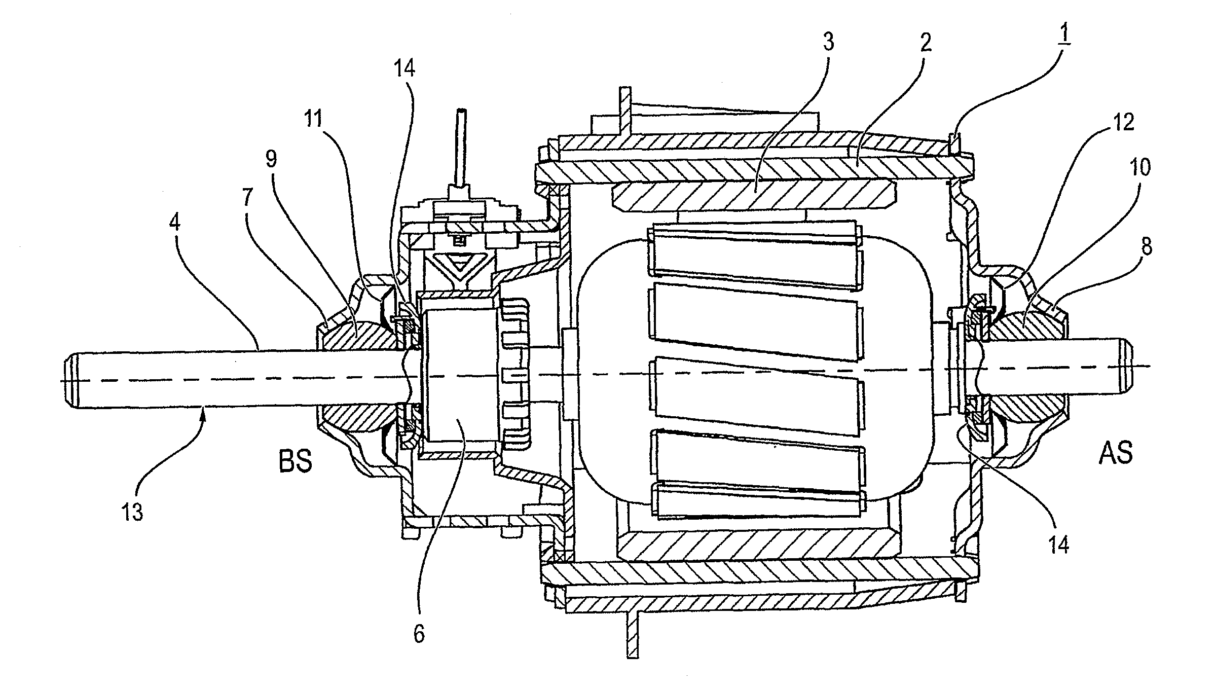
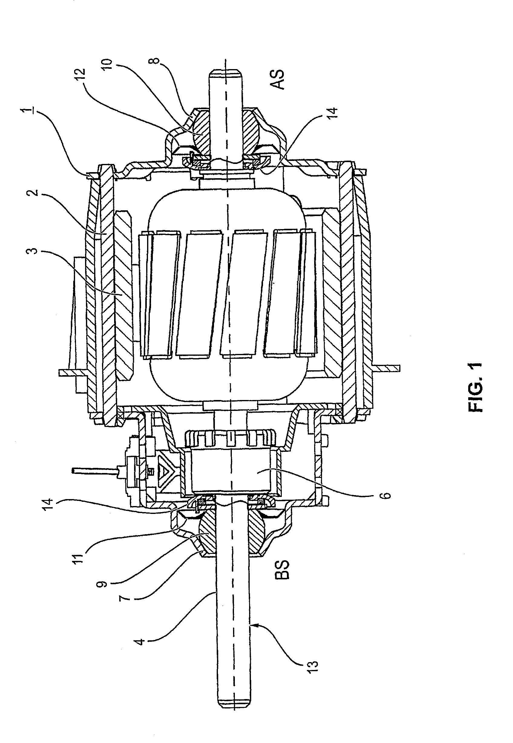
[0031]FIG. 1 shows an electric motor drive in the form of a commutator motor 1 with a motor housing (pole housing) 2, on whose inner circumference are held a number of curved field or permanent magnets 3 corresponding to the number of poles of the motor 1. In a manner that is not illustrated in detail, a motor shaft 4 bears the armature (rotor) 5 of the commutator motor 1, which is implemented as a rotor lamination stack with rotor windings wound therein. In a manner that is not illustrated in detail, a commutator 6, likewise mounted on the motor shaft 6, has commutator bars with bar connections that are connected to the rotor windings of the armature 5. The bars of the commutator 6 are contacted by brushes in a manner known per se. This side of the motor is frequently also called the brush side or brush system side, or abbreviated BS (BS side). The opposing side is labeled AS (AS side).

[0032...


PUM


Abstract

An electro-motor drive, in particular for a fan drive of a motor vehicle, includes a commutator motor, a motor shaft of which is rotatably mounted on axially opposite sides in shaft bearings facing away from the bearing shield in order to substantially dampen the sound of at least bearing play-related contact noise and vibration or humming noise.

Description


Claims


Application Information

Patent Timeline
Owner BROSE FAHRZEUGTEILE GMBH & CO KG HALLSTADT (DE)
Learn More